PT100 Sensor Wiring

Joined
14 Dec 2008
Messages
140
Reaction score
1
Location
Stirlingshire
Country
United Kingdom
Hi,

I'm a little confused with something and hopefully you guys will be able to help.

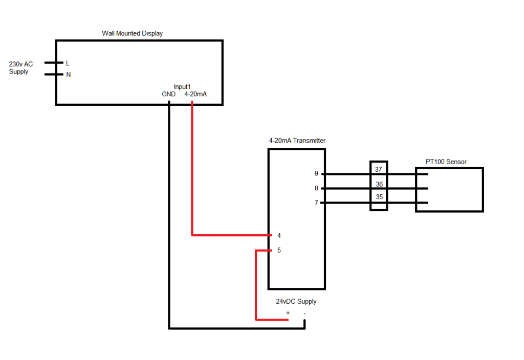
I have been given a little project to do, but I am confused by this wiring diagram:
pt100.png


I have a:
PT100 sensor
4-20mA transmitter
Digital Display (temperature)

From the above circuit diagram, I see that the PT100 sensor will go in to terminals 7, 8, 9.

The transmitter needs a 24vDC supply, and the digital display gets it signal from two wires from the transmitter.
- The power supply (Vs) looks like it uses terminal 5 for the positive, but I don't understand the rest. Where do I connect 0V to, and where do I connect the cable with two wires in to feed the display?


Thanks a lot
 
Sponsored Links
Look up the data for 4 to 20 mA signalling.

The temperature sensor output is the amount of current that it takes from the 24 volt supply. Higher the temperature the more current it takes. The minimum is 4 mA and the maximum 20 mA

The range may be 0 deg = 4 mA to 100 deg = 20 mA

or it could be -100 deg = 4 mA to 500 deg = 20 mA

The display measures the current flowing through it from the sensor and converts it into a display that may or may not be the temperature measured. It will not be if the range the sensor does not match the range in the display.

Most modern displays take their power from the current flowing through them.
 
If you have a resistance decade box you can calibrate the transmitter to give your 4-20mA quite easily for a PT100. A decade box would connect with one side to both 7 and 8, the other side to 9.
For 0-100 °C it is simply a case of putting in 100 ohms to give 0°C and 138.5 ohms for 100°C.
For anything else within reason a fag packet calculation is 0.385 ohms per °C and add 100 ohms, have used this for around the 0 to 150°C mark. Outside this or to be more precise just use the tables.

As bernard says, the supply connects, as in your diagram Vs+ and -.
Your gauge goes where it says loop load.

Gold star to anyone who can say why there are three wires to the PT100 detector :)
 
I would claim the gold star but I will wait to see who comes up with the answer.

In the old days it used to be four wires before the cost of electronic components allowed for more complex analogue circuitry to be economic to produce.
 
Sponsored Links
I have only ever used 3 wire, have heard of 4 wire systems tho.
Brings back memories of using wheatstone bridges and galvanometers!!
 
Hi,

Thank you very much for the replies!

It has helped me understand it a bit more (I think).

The display is quite large, so has a 230v supply for itself, and then has the 4-20mA input to give the temperature range, which is 0-300C in this case.

So am I correct in saying that the Loop Load on the wiring diagram is infact the input on the display?


Thanks a lot :)
 
The 4 - 20 ma system allows power and data down same pair of wires. 0 - 4 ma drives the unit and 4 - 20 ma is data out. In other words does not begin to measure until after 4 ma.

Used a lot with PLC's the analogue inputs are designed for 4 - 20 ma units. Can't see point of using 4 - 20 ma unit if not feeding a PLC.

4-20mA is an industry standard, it may not be massively important in the case above but there are a number of reasons for using it in industry.
A couple which spring to mind are it is relatively fail safe i.e. if you have 0mA there is a fault somewhere (floating zero) and a current driven circuit does not have the same limitations as a voltage driven system i.e. volt drop caused by resistance of the wiring.
Dead easy to derive a 1-5v from too using a 250R resistor.
I wouldn't really class the above system as a data system in the computer respect, all it is doing is providing an analogue signal relative to the temperature measuring device input. I have come across data systems that do use 4-20mA loops with old equipment, usually to overcome the distance limitations of RS232
 
Hi,

So am I correct in saying that the Loop Load on the wiring diagram is infact the input on the display?

Thanks a lot :)

The "loop load" on your diagram is the digital display.
It could quite as easily be another type of instrument, controller for example.

As you've said, the digital display has its own power supply, sorted!
There will (probably) be a + (plus) and - (minus) on the digital display input terminals.
The wire from "SEM1603P" terminal 4 goes into the + (plus) terminal on the digital display.
The wire from the - (minus) terminal on the digital display goes back to the - (minus, or negative) terminal of your 24v supply.
The earth symbol can just lead to confusion sometimes, its just telling you the negative line should be tied to earth.

4-20mA signals was for safety, if the wire was cut, you would loose the 4mA, therefore the system would "know" something was wrong and provide an alert.
As Spark123 says it's the industry standard. There was more than one but 4-20mA is so versatile with inherent safety too.

Nowadays you could find all sorts of signals superimposed onto the 4-20mA in industrial control situations. Usually large computer controlled plant (but not limited to).

If you search internet you'll find temperature/resistance tables for your temperature sensor. "PT100 resistance table" should do it.
 
Thank you all very much for the help! It has helped me greatly.

Just to confirm (for my brain), is this how it should be wired up?

Display.png


Thanks a lot
Ryan
 

DIYnot Local

Staff member

If you need to find a tradesperson to get your job done, please try our local search below, or if you are doing it yourself you can find suppliers local to you.

Select the supplier or trade you require, enter your location to begin your search.


Are you a trade or supplier? You can create your listing free at DIYnot Local

 
Sponsored Links
Back
Top