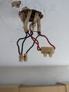
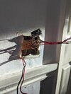
Good Afternoon all, Got a bit of a question or two here regarding 2 Way switching of two lights on two floors which I hope someone can clarify.
Background:
Starting with a bit of background to the story, Had a new bathroom put in back in 2019, as part of this the Consumer Unit was swapped out for a (at the time 17th Ed) unit with RCD Protection etc. This was done by a subcontractor from the bathroom fitter/supplier. The old unit was a rewireable fuse Wylex unit.
Originally I believe both upstairs and downstairs circuits were on the same fuse, when the new board was installed I recall the guy splitting it into two, once per RCD. this was fine until he tried to use the 2 way switches on the stairs (yes I can hear you all screaming borrowed Neutral, and yes we will come to that). Anyway his solution was to just put both circuits on separate MCBs on the same RCD.
So up until now everything has worked fine, no issues but ive always had a niggle at the back of my head that something was bodged here (to be honest, the whole bathroom has been a fiasco, constant leaks, supplier saying nothing wrong with it, yet 3rd party builders etc saying yep its a install issue) Anyway back on track. I fitted some new replacement lights in one of the rooms, this is a room with two lights, and one 2 gang switch. Removing one light i found just a single T&E so assumed it to be end of line but also thought it was odd as there was no loop to the switch. The other light in the same room had the expected 3 sets of T&E but as you find in a old house noting was labelled and no sleaving to mark the switch line so I took the time to trace the cables to see what was what and mark them up for the next guy or even myself in future. Now this is where I get some questions.
1. first light has 3 cables, as I would expect, 1. line in, 2. Line out to a light fitting under the stairs 3. switch
Now, in the 2 gang switch, one controls one light and the other the second light. so I was expecting 2 sets of T&E. one per light. but no in this case its one set which I traced back to the 1st light and is connected as expected. the second switch has a bridge wire, between the line (common) terminal on the first switch to the second Common terminal. ok so yes that technically is connected the same way as a 3 plate would be electrically but not in the light itself, however it then has a single red wire leave the L1 terminal into the wall, I assume this goes to the second light via a Junction box above the ceiling and the neutral goes back to the other light somehow probably via the same JB. Assume they are both on the same light circuit neutral too.
First question is, Is this allowed? i.e. the Single red wire off to another light bridged from the first switch?
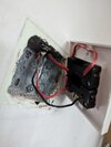
I don't see this style of wiring in any of the Regs or any guides / diagrams i found. the single wire does look to be double insulated, as it seemed to have one layer of insulation, then a second layer over the top, house is from the 60s i think and this is all the old red and back colours, does not look to be rubber cable but PVC at least.
I am tempted to try and replace the T&E from the first light to the switch if i can find a way to do so without ripping up floors etc as who ever fitted it cut the CPC off almost flush with the top of the back box and left it like that. (none of the sockets/switches etc in the house have sleaving), Ive managed to use a chockblock to attach a length of CPC to the existing one and to the metal back box and connectivity is there now to the CPC in the light and the rest of the house but think it may be better to replace the cable if possible so its done properly.
so if I'm doing that do I think i may also replace that single wire with a T&E and loop in on the second switch properly or just drop the second switch completely and connect the second light in parallel to the first on a single gang switch. both lamps are in same room, in line with each other and look to both be the same side of the joists so maybe easy to pull a cable between the two lamps that way.
This leads me onto the second question, while tracing the cables, I ended up looking at the under stairs light that the first light above loops into (or so I thought, being the next physical light in a line). Tracing this it turn out it does not go directly to that light but past it, into the lower stairs light loop and back out to the fitting under the stairs, this then has a second T&E go to a 2 Gang switch by the door and is wired as I would expect. Now the interesting bit. in this 2 gang switch there is 3 sets of T&E (again all red and black). and its connected as follows:
cable 1 - from understairs light -> 1st gang switch - seems to be wired as expected, line in and sl back out to the lamp.
cable 2 - red into L1 and black in L2, a bridge wire from the first gang live to the common, of this gang. I traced this to the 2 gang switch upstairs that also controls the stair lights.
Cable 3 - Red goes into the second Gang common and sends a line off up to "somewhere" with the black not connected at all (taped off). (ive traced this cable by lifting a floor board and it ended in a chockblock under the floor going nowhere) so disconnected the line from the switch so its dead. not yet removed it as it seems stuck in the wall.
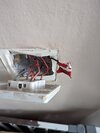
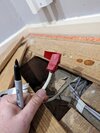
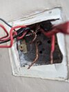
Right, now the second 2 gang switch upstairs has cable 2 coming into its second gang L1 and L2, with two sets of T&E coming out the common, (first gang is for the bathroom lights, comes from a junction box in the loft and is wired as expected for a loop in setup).
So question here is can two circuits be in the same switch? bathroom lights fed from upstairs circuit, two way switch from the switch below via the bridge wire. Guess its allowed as the two circuits are not electrically connected, just share the same physical switch assembly. also means safe isolation would require both upstairs and downstairs MCBs to be off.
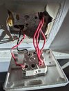
Does this require some sort of labelling? I know this is the case but say joe blogs came over and decided to swap out the switch to a nice new one and didn't know there is two separate circuits sharing the same physical switch assembly they would be in for a bit of a shock if they assumed it was all on the upstairs MCB as thats where the switch is. I know a pro would follow safe isolation procedures and confirm dead properly so this is more a question should joe bloggs do some diy.
Now back to this 2 way switching setup. as stated above. switch 1 on the ground floor has a line supplied to the Common terminal and a second cable from L1 and L2 to the same terminals on this upstairs switch. again no sleaving to identify the black is used as a strapper.
From the Common of this second switch leaves 2 sets of T&E, both with their black wire cut off! one goes back down the wall, under the floor and to the lower stairs lamp, the black is left unconnected. so this makes sense once you know where the wires go, but feel this is not best practice even for older wiring.
Is this kind of two way switching allowed? Current regs say use 3 core T&E for this, but I know its possible to use the way its wied now if it was done with single wires conduit style. should this be left this way or upgraded to the 3 core method or split back to a 1 setup? I can see why they did this as it leads on to my next question.
The second T&E with the black cut off also comes from the Common on the upstairs switch into the loft, along and into the upstairs lamp. a second T&E from here then goes to the same junction box in the loft the bathroom light are connected to. this time the red wire is cut off. you can see where this is going, so the upstairs light takes its feed via the two switches, do returns it to the neutral of the upstairs circuit. hence a shared / borrowed neurtral and why the installer had issues with the RCDs tripping. (also the guy installing the fan etc never put the cover bac on the JB, probably due to to many Cables going in to it. (6)
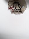
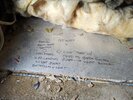
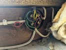
So this needs to be addressed ASAP, now I can remove the neutral from the junction box, and run it down to the ground floor stair light via the cut off unconnected black wires with very little issue as the cable is there, just not connected at each end and just needs them to be connected together at the upstairs switch. thus putting it on the same circuit as the ground floor light and fixing the borrowed neutral issue. my question is, would that be ok to have an upstairs plysically located light on the downstairs circuit. or do i just split it back to 1 way? secondly can this sort of wire layout be allowed? unless you know how its connected it could be confusing to anyone looking at it?
Background:
Starting with a bit of background to the story, Had a new bathroom put in back in 2019, as part of this the Consumer Unit was swapped out for a (at the time 17th Ed) unit with RCD Protection etc. This was done by a subcontractor from the bathroom fitter/supplier. The old unit was a rewireable fuse Wylex unit.
Originally I believe both upstairs and downstairs circuits were on the same fuse, when the new board was installed I recall the guy splitting it into two, once per RCD. this was fine until he tried to use the 2 way switches on the stairs (yes I can hear you all screaming borrowed Neutral, and yes we will come to that). Anyway his solution was to just put both circuits on separate MCBs on the same RCD.
So up until now everything has worked fine, no issues but ive always had a niggle at the back of my head that something was bodged here (to be honest, the whole bathroom has been a fiasco, constant leaks, supplier saying nothing wrong with it, yet 3rd party builders etc saying yep its a install issue) Anyway back on track. I fitted some new replacement lights in one of the rooms, this is a room with two lights, and one 2 gang switch. Removing one light i found just a single T&E so assumed it to be end of line but also thought it was odd as there was no loop to the switch. The other light in the same room had the expected 3 sets of T&E but as you find in a old house noting was labelled and no sleaving to mark the switch line so I took the time to trace the cables to see what was what and mark them up for the next guy or even myself in future. Now this is where I get some questions.
1. first light has 3 cables, as I would expect, 1. line in, 2. Line out to a light fitting under the stairs 3. switch
Now, in the 2 gang switch, one controls one light and the other the second light. so I was expecting 2 sets of T&E. one per light. but no in this case its one set which I traced back to the 1st light and is connected as expected. the second switch has a bridge wire, between the line (common) terminal on the first switch to the second Common terminal. ok so yes that technically is connected the same way as a 3 plate would be electrically but not in the light itself, however it then has a single red wire leave the L1 terminal into the wall, I assume this goes to the second light via a Junction box above the ceiling and the neutral goes back to the other light somehow probably via the same JB. Assume they are both on the same light circuit neutral too.
First question is, Is this allowed? i.e. the Single red wire off to another light bridged from the first switch?

I don't see this style of wiring in any of the Regs or any guides / diagrams i found. the single wire does look to be double insulated, as it seemed to have one layer of insulation, then a second layer over the top, house is from the 60s i think and this is all the old red and back colours, does not look to be rubber cable but PVC at least.
I am tempted to try and replace the T&E from the first light to the switch if i can find a way to do so without ripping up floors etc as who ever fitted it cut the CPC off almost flush with the top of the back box and left it like that. (none of the sockets/switches etc in the house have sleaving), Ive managed to use a chockblock to attach a length of CPC to the existing one and to the metal back box and connectivity is there now to the CPC in the light and the rest of the house but think it may be better to replace the cable if possible so its done properly.
so if I'm doing that do I think i may also replace that single wire with a T&E and loop in on the second switch properly or just drop the second switch completely and connect the second light in parallel to the first on a single gang switch. both lamps are in same room, in line with each other and look to both be the same side of the joists so maybe easy to pull a cable between the two lamps that way.
This leads me onto the second question, while tracing the cables, I ended up looking at the under stairs light that the first light above loops into (or so I thought, being the next physical light in a line). Tracing this it turn out it does not go directly to that light but past it, into the lower stairs light loop and back out to the fitting under the stairs, this then has a second T&E go to a 2 Gang switch by the door and is wired as I would expect. Now the interesting bit. in this 2 gang switch there is 3 sets of T&E (again all red and black). and its connected as follows:
cable 1 - from understairs light -> 1st gang switch - seems to be wired as expected, line in and sl back out to the lamp.
cable 2 - red into L1 and black in L2, a bridge wire from the first gang live to the common, of this gang. I traced this to the 2 gang switch upstairs that also controls the stair lights.
Cable 3 - Red goes into the second Gang common and sends a line off up to "somewhere" with the black not connected at all (taped off). (ive traced this cable by lifting a floor board and it ended in a chockblock under the floor going nowhere) so disconnected the line from the switch so its dead. not yet removed it as it seems stuck in the wall.


Right, now the second 2 gang switch upstairs has cable 2 coming into its second gang L1 and L2, with two sets of T&E coming out the common, (first gang is for the bathroom lights, comes from a junction box in the loft and is wired as expected for a loop in setup).
So question here is can two circuits be in the same switch? bathroom lights fed from upstairs circuit, two way switch from the switch below via the bridge wire. Guess its allowed as the two circuits are not electrically connected, just share the same physical switch assembly. also means safe isolation would require both upstairs and downstairs MCBs to be off.

Does this require some sort of labelling? I know this is the case but say joe blogs came over and decided to swap out the switch to a nice new one and didn't know there is two separate circuits sharing the same physical switch assembly they would be in for a bit of a shock if they assumed it was all on the upstairs MCB as thats where the switch is. I know a pro would follow safe isolation procedures and confirm dead properly so this is more a question should joe bloggs do some diy.
Now back to this 2 way switching setup. as stated above. switch 1 on the ground floor has a line supplied to the Common terminal and a second cable from L1 and L2 to the same terminals on this upstairs switch. again no sleaving to identify the black is used as a strapper.
From the Common of this second switch leaves 2 sets of T&E, both with their black wire cut off! one goes back down the wall, under the floor and to the lower stairs lamp, the black is left unconnected. so this makes sense once you know where the wires go, but feel this is not best practice even for older wiring.
Is this kind of two way switching allowed? Current regs say use 3 core T&E for this, but I know its possible to use the way its wied now if it was done with single wires conduit style. should this be left this way or upgraded to the 3 core method or split back to a 1 setup? I can see why they did this as it leads on to my next question.
The second T&E with the black cut off also comes from the Common on the upstairs switch into the loft, along and into the upstairs lamp. a second T&E from here then goes to the same junction box in the loft the bathroom light are connected to. this time the red wire is cut off. you can see where this is going, so the upstairs light takes its feed via the two switches, do returns it to the neutral of the upstairs circuit. hence a shared / borrowed neurtral and why the installer had issues with the RCDs tripping. (also the guy installing the fan etc never put the cover bac on the JB, probably due to to many Cables going in to it. (6)


So this needs to be addressed ASAP, now I can remove the neutral from the junction box, and run it down to the ground floor stair light via the cut off unconnected black wires with very little issue as the cable is there, just not connected at each end and just needs them to be connected together at the upstairs switch. thus putting it on the same circuit as the ground floor light and fixing the borrowed neutral issue. my question is, would that be ok to have an upstairs plysically located light on the downstairs circuit. or do i just split it back to 1 way? secondly can this sort of wire layout be allowed? unless you know how its connected it could be confusing to anyone looking at it?


