You are using an out of date browser. It may not display this or other websites correctly.
You should upgrade or use an alternative browser.
You should upgrade or use an alternative browser.
6mm cable cooker
- Thread starter Ashbou10
- Start date
Sponsored Links
- Joined
- 27 Jan 2008
- Messages
- 24,903
- Reaction score
- 2,877
- Location
- Llanfair Caereinion, Nr Welshpool
- Country

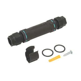
There are loads of methods
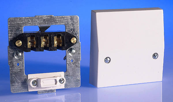
 but main point is the physical protection, in the main though would use a cooker connection unit
 as it also marks where the cable runs so complies with safe routes.


If you use butt connectors then you’ll need a proper ratchet crimper. Even then, crimps on solid conductors aren’t the most reliable, I would avoid crimps for a high current application like this. you’d also need a BLUEcrimp for the earth wire, because it’s a different size.
Wago do a connector that goes up to 6mm². May be the better solution?
Wago do a connector that goes up to 6mm². May be the better solution?
Sponsored Links
Best way is to solder them and cover with heat shrink then self amalgamating tape.
Winston... Have you ever actually tried to do that ?
If you did and it was successful can you provide detailed instructions.
I don't think I'd advise a DIYer to attempt that.Best way is to solder them and cover with heat shrink then self amalgamating tape.
I'm not particularly sure I'd want to bother with all that anyhow, sounds a load of effort for something that's going look a mess.
Winston... Have you ever actually tried to do that ?
If you did and it was successful can you provide detailed instructions.
Many times. I don’t need to tell you how to solder surely.
You could tell the op.
For instance, would the op need to twist the strands together, or what?
Some soldering techniques differ, I have seen people remove several inches of insulation to make some very pretty knots before soldering.
Yet this wouldn't be possible where cable length is limited.
How would the op solder these cables to get a good solid joint that isn't going to break?
I don't think I'd advise a DIYer to attempt that.
I agree, definitely not something I would advise.
Many times. I don’t need to tell you how to solder surely.
Just tell me how you put the heat shrink onto the conductors before soldering them and keep the heat shrink sleeve cool enough that it does not shrink before it can be sld over the soldered joint.
It can be done but requires a lot of the cable's sheath to be removed so the the heat shrink can put on the conductors before soldering and kept away from the heated area of copper until the soldering is completed..
to replace the cable sheath that had to be removedthen self amalgamating tape.
Or are you advocating this type of soldered joint where the heat shrink does not have to be put on the conductors until after the joint has cooled
I think the wires are so thick you need to get a lot of heat in. And somehow prevent the heat shrinking before you want it to.
And put a layer of heat shrink to replace the grey sheeth
And put a layer of heat shrink to replace the grey sheeth
Why have i always been told you cant solder 230v. I do a lot of soldering on cars 12v system and now im reading on this to just solder. What's the difference soldering on the 230v or 12v is the solder different or something
Who ever told you that was wrong. Many electronic devices have numerous soldered joints in them and some have voltages inside them well in excess of 230v.
Re the various 'how to solder posts above' it appears you are experienced at soldering so I won't elaborate further.
it appears you are experienced at soldering so I won't elaborate further.
Is that because you cannot elaborate on your statements about soldering 6 mm conductors
Is that because you cannot elaborate on your statements about soldering 6 mm conductors
Nope. I have been soldering for well over 60 years and know how to do with even bigger stuff that 6mm conductors.
DIYnot Local
Staff member
If you need to find a tradesperson to get your job done, please try our local search below, or if you are doing it yourself you can find suppliers local to you.
Select the supplier or trade you require, enter your location to begin your search.
Please select a service and enter a location to continue...
Are you a trade or supplier? You can create your listing free at DIYnot Local
Sponsored Links
