I'm having an issue with a biasi Riva boiler. There is a 3 wire stat that's been installed and it looks as if they were using the "neutral" of the stat as the switch wire to the boiler. The boiler won't fire in CH but will in DH. I've linked the stat out at the boiler and it still doesn't fire leading me to think the PCB is faulty. Any ideas?
You are using an out of date browser. It may not display this or other websites correctly.
You should upgrade or use an alternative browser.
You should upgrade or use an alternative browser.
Biasi Riva thermostat issue.
- Thread starter minch80
- Start date
Sponsored Links
post a pic of the wiring at the thermostat, a blue wire does not nececerilly mean it is a neutral, it is common to use a blue wire as a switched live, if you have HW it is unlikely to be the PCB
D
Deleted member 267285
Which thermostat?
It's an old sunvic one, I'd gone to replace the stat as it was faulty, checked and there were 3 wires, live , switch live and neutral. When I checked at the boiler the wires connected to live and neutral were across 1 and 3 at the boiler. There's 240 across those terminals but when you short them out nothing happens, no pump or fan start.
Sponsored Links
it looks as if they were using the "neutral" of the stat as the switch wire to the boiler.
I assume you are referring to the wire colours here, and by neutral you are referring to the blue wire. What a wire is connected to determines what it is, not the colour of its insulation. But as you will see below, that actually may be the correct colour to use.
You don't give details of your specific model but if it's a Riva Plus HE Combi, from the manual below, you can see that rather unusually it shows a neutral for switching purposes. But the operating principle is the same as if it was a live. When terminals 1 & 3 are electrically connected together, either with a link or via a thermostat that is in the 'call for heat' condition, the boiler should run the central heating, and when they are not connected together it shouldn't.
However if a link is inserted between 1 and 3 as per fig 6.16 then the boiler should fire up the central heating.
Then there's the mysterious 3rd wire you mention. If, it is a live that has been used to operate a small accelerator heater inside the old Sunvic and you have connected it to the boiler's thermostat terminals and as per the note in the red box, that's not something you should do and it may have damaged the boiler. This is just a theory of course, when you post the photos as requested we may have a better idea.
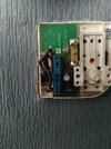
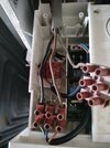
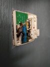
Sorry for the delay, the boiler is at my uncles and I needed time to get back. I've attached pictures showing the wiring of the stat and the boiler hopefully this makes more sense about what I was describing. For reference I've come to just swop the stat and couldn't get a normal stat to work.
Attachments
D
Deleted member 267285
Yes, the time clock could be preventing it working, I don’t understand some of the wiring though. What does appear to be neutral is in a separate terminal strip than anything else - that said, it should still work on live and switch.
How was the old stat faulty? Was the C/H partially working with the old stat, before the attempt at exchanging it for a new one?It's an old sunvic one, I'd gone to replace the stat as it was faulty, checked and there were 3 wires, live , switch live and neutral
And if, as @stem has suggested, you have a switched neutral; then that's just asking for trouble IMO!
However, the 'N' Stem highlighted in the screenshot, is just named as 'link N' - having alphabetically followed on from 'loosen the screws M' - it doesnt represent 'Neutral' (although it could be a happy coincidence)!
I believe the connector block is designed for a volt-free switching stat, even though it appears to be switching neutral.
Which stat did you try and swap out?For reference I've come to just swop the stat and couldn't get a normal stat to work.
If you did manage to short a live and neutral, there appear to be two fuses on the PCB - it may be worth checking those...
EDIT - I haven't found the exact model of your Sunvic thermostat, but most versions show these type of connections -
Where 1 is L, 3 is SL and 4 is N.
Your connections within the boiler appear to show 1 and 4 connected to the boilers external control connector block, with the switched live (grey wire), connected to another block, that we can't see any connections to.
If the stat really was working with these connections, the circuit may have been made through the accelerator heater!
If you do intend to connect a new stat, the safest way would be to run one cable to power the stat and a separate one, purely for the switching; connecting the external control connector block, to the stats volt-free contacts.
The reuse of the old stat and legacy wiring, has certainly caused me some confusion!
...Not to mention Biasi's use of brown and blue wires on a connector block that requires a link to operate!
Last edited:
For the sake of curiosity...
If the PCB does match yours, And the connections here match...

Then the thermostat connection block is Live switching.
The black wire on the 'external control' terminal block is unused (for a frost stat).

If the C/H still doesn't work with a link in, then as has been said earlier, it looks likely to be either the time clock, or unfortunately, damage to the PCB.
If the PCB does match yours, And the connections here match...
Then the thermostat connection block is Live switching.
The black wire on the 'external control' terminal block is unused (for a frost stat).
If the C/H still doesn't work with a link in, then as has been said earlier, it looks likely to be either the time clock, or unfortunately, damage to the PCB.
Last edited:
However, the 'N' Stem highlighted in the screenshot, is just named as 'link N' - having alphabetically followed on from 'loosen the screws M' - it doesnt represent 'Neutral' (although it could be a happy coincidence)!
I wondered about that initially, but written in the instructions and printed in large letters under under the wiring diagram it says
If you can't connect live wires, I can't think what else other than a neutral could be connected to them???..... unless they mean don't connect live wires from an external source. Bit of an odd thing to say though.....unless I've missed something......
Very unusual for heating controls to use a neutral for switching though, I've never seen it before. Easy to check if it's a live or a neutral with a multimeter though. I would be interested to know for sure.
I have a feeling it means external source - a separate live coming from the stat would completely bypass the boilers internal fuse.unless they mean don't connect live wires from an external source. Bit of an odd thing to say though.
But yes, odd choice of words by Biasi, a coincidental use of N for labeling and an odd choice of colour; using blue for a switched live cable.
Adding up to a perfect storm, when you include a legacy stat and wiring!
I wondered about that initially, but written in the instructions and printed in large letters under under the wiring diagram it says
View attachment 312746
If you can't connect live wires, I can't think what else other than a neutral could be connected to them???..... unless they mean don't connect live wires from an external source. Bit of an odd thing to say though.....unless I've missed something......
Very unusual for heating controls to use a neutral for switching though, I've never seen it before. Easy to check if it's a live or a neutral with a multimeter though. I would be interested to know for sure.
I have a feeling it means external source - a separate live coming from the stat would completely bypass the boilers internal fuse.
But yes, odd choice of words by Biasi, a coincidental use of N for labeling and an odd choice of colour; using blue for a switched live cable.
Adding up to a perfect storm, when you include a legacy stat and wiring!
Agreed both the MIs of the Riva plus calling the wire to the room stat N is wrong, if you look at the MIs attached for the Riva Compact they call the same wire M, so it isnt a neutral, I think it is volt free switching hence why no Live to be connected, never wired one though so cant really say, why there was a third wire in the origional stat I have no idea, as already suggested simple test is remove the wires and replace the origional link
it will be the time clock they are notorious on this model, might not be faulty but a nightmare to switch on to manually on, never mind set the times , but also very unreliable most Biasis I see have an external timer simply for that reason and the old one linked outFor the sake of curiosity...
If the PCB does match yours, And the connections here match...
View attachment 312735
Then the thermostat connection block is Live switching.
The black wire on the 'external control' terminal block is unused (for a frost stat).
View attachment 312736
If the C/H still doesn't work with a link in, then as has been said earlier, it looks likely to be either the time clock, or unfortunately, damage to the PCB.
DIYnot Local
Staff member
If you need to find a tradesperson to get your job done, please try our local search below, or if you are doing it yourself you can find suppliers local to you.
Select the supplier or trade you require, enter your location to begin your search.
Please select a service and enter a location to continue...
Are you a trade or supplier? You can create your listing free at DIYnot Local
Sponsored Links
Similar threads
- Replies
- 3
- Views
- 3K
- Replies
- 9
- Views
- 2K


