Danfloss 102 Replacement

Joined
21 Nov 2015
Messages
5
Reaction score
0
Country
United Kingdom
I currently have a Danfloss 102 controlling my heating and water. I want to replace this with a programmer that'll allow me to control the timings of my heating and hot water separately. The compatability tables seem to suggest that I can only replace a 102 with a programmer that can't have only heating or water on at one time. I want to be able to have my central heating on without my water being heated up at the same time wasting energy.

Any help please?
 
Sponsored Links
It depends on the rest of the system whether you will be able to do this. Most likely you have gravity hot water and pumped central heating.

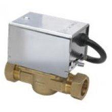
Are there any motorised valves in the system similar to this...


image.jpeg
Thanks for the reply. I have a blue box that looks similar to that. It has a switch with W H and M on. It's slid to W.
Looks like this.
 
That looks promising. Are you happy doing any mains voltage rewiring if necessary?

If so, can you post pictures of the wiring behind the Danfoss 102 and also the inside of the wiring centre where all the controls etc are connected together?
 
Sponsored Links
Sorry it's been a while. But now the weather is cold sorting out a decent heating programmer seems more important.

I've taken a picture of the wiring inside. I'm no expert but I'd do any rewiring myself.

There are two main cables going into the programmer. One of them connects to the Earth, neutral and a small red wire going into the 'Com' connection. The other cable connects to all of them except the 'Com' connector.

I've sent a picture of the base plate and the connections as best I can.
 

Attachments

  • image.jpeg
    image.jpeg
    90.8 KB · Views: 203
  • image.jpeg
    image.jpeg
    90.8 KB · Views: 173
Don't forget the brown link between COM and Live.

Edit: I just can't ignore the fact that that wiring is so untidy, why is there a floating junction box on that mid position valves flex? BG seem to do that a lot for some reason, even when the valve flexes are long enough. I've seen them do it twice with connector blocks and tape. Those blue valves are made specially for BG as well. I hope there is strain relief on those cables to the programmer, and it would be nice if the conductors were correctly identified with coloured sleeving.

It should be straightforward to convert to a standard Y plan, you will likely only need to add 1 more wire from the new programmer to the valve for the hot water off connection, which is not available on your current programmer.
 
Last edited:
I had nothing to do with any of this wiring. It was like it when I moved in a year ago.

I'm sorry to ask but what is a 'Y plan'? Is that one where the central heating and water controls are separate? And also, how do I ADD 1 more wire? Is that an easy task? From what I see and can work out, I only have central heating ON and water ON wires.

Thanks.
 
A Y plan heating system uses a mid position valve (that blue thing in your photo) to route hot water from the boiler to the hot water cylinder, to the radiators, or to both at the same time. Your programmer as you have correctly identified only has HW on and CH on. To get a mid position valve to close off the HW so you have the option of heating without hot water, you need to provide a HW off signal from the programmer. (the extra wire needed) The thermostat fitted to the hot water cylinder already has a HW off connection and will close the HW part of the valve when the cylinder has reached its set temperature.

As to altering it, is the central heating wiring centre (large junction box), the blue valve and programmer in the same cupboard? I can't tell from your photo. Where does the flat cable going to the programmer go to? It looks like it could be the mains supply from the central heating fused spur.

Also please post a clear photo of inside the wiring centre as requested above, and 1 photo of a general view of the cupboard, just so we can spot if anything major is wrong with anything else!

See here for Y plan wiring diagram.
 
Thanks for your replies.

The flat wire runs up into the loft and then runs around before disappearing again above the front door area.

I'm sorry but I'm not sure I've found the wiring centre. One of the wires to the programmer is the flat one which disappears and the other comes from a fused socket next to it. Would the centre be in the airing cupboard somewhere? Or do I need to look elsewhere?

Sorry if I'm asking silly questions. I'm trying to learn.
 

Attachments

  • image.jpeg
    image.jpeg
    108.2 KB · Views: 154
  • image.jpeg
    image.jpeg
    97.2 KB · Views: 151
It looks like your 'wiring centre' is just a single box with a blank plate, the one between the 2 switches. Looking at the state of your existing wiring, I'm going to recommend calling an electrician to correctly identify everything as your layout is not standard. There is also a range of electrical defects visible, and that is without the covers removed!

It should however be very easy for a decent electrician to sort, but will take pages of explaining on here!

Where in the country are you? Someone here may be local to you and be able to help.

Why has every central heating system on here lately had terrible wiring? It really isn't difficult!!
 
I'm sorry to ask but what is a 'Y plan'?
Freddo is right, it's not easy to explain in writing, and you will need to have a good working knowledge of electrical circuits to understand it. There's a great interactive 'Y Plan' wiring schematic here. By clicking on the various states of the system you can see what wires should be live and when. If you click on the 'Central Heating only' schematic, you will see a light blue flashing line to highlight a wire from the programmer marked 'HW off'. This is the wire you do not have. It also needs to be connected to the cylinder thermostat.

Why has every central heating system on here lately had terrible wiring?
Indeed. Probably because whoever installed the system didn't want to pay for the services of a professional, and among professional electricians some don't understand the circuits associated with heating systems. This one is particularly bad because not only is the cable not secured, and the cable sheath does not extend inside the programmer, but there are exposed live wires with 'whiskers'. This design of programmer is not suitable for being mounted outside of an enclosure, because it is not equipped with a terminal cover, or cable grips.
 
I've not seen those diagrams before, they are now bookmarked.

Also how can anyone call themself a professional electrician if they can't wire a standard domestic heating system?! We were taught that at college!
 

DIYnot Local

Staff member

If you need to find a tradesperson to get your job done, please try our local search below, or if you are doing it yourself you can find suppliers local to you.

Select the supplier or trade you require, enter your location to begin your search.


Are you a trade or supplier? You can create your listing free at DIYnot Local

 
Sponsored Links
Back
Top