Double switched light wiring

Joined
2 Apr 2008
Messages
200
Reaction score
1
Location
Hampshire
Country
United Kingdom
Hi folks,

I've just moved into a new house and there are some interesting wiring arrangements which I'll gradually sort out over time. First job is the hall/stairs/landing lights. In short the house has 5 levels, each half a level above the previous. Call them levels 1-5. There are landing lights on levels 2 and 4 and switches on 1 (single), 3 (double) and 5. Switches 1 and 3a control light 2. Switches 3b and 5 control light 4. Hope that makes sense.

The problem is that both of these are wired in the same, weird way, such that there is only one combination of the two switches which makes each light come on. Not the usual (useful) case where throwing either switch changes the state of the light.

There is the normal three-core+earth cable which you would imagine would be everything that was needed to have a proper double-switched light and I'm hoping it's just been put back together wrongly at some point in the past.

The wiring at the top of the lamp offers no clue - it just has red+black+earth - the "clever" stuff is apparently done elsewhere and is inaccessible (for now) under the floor.

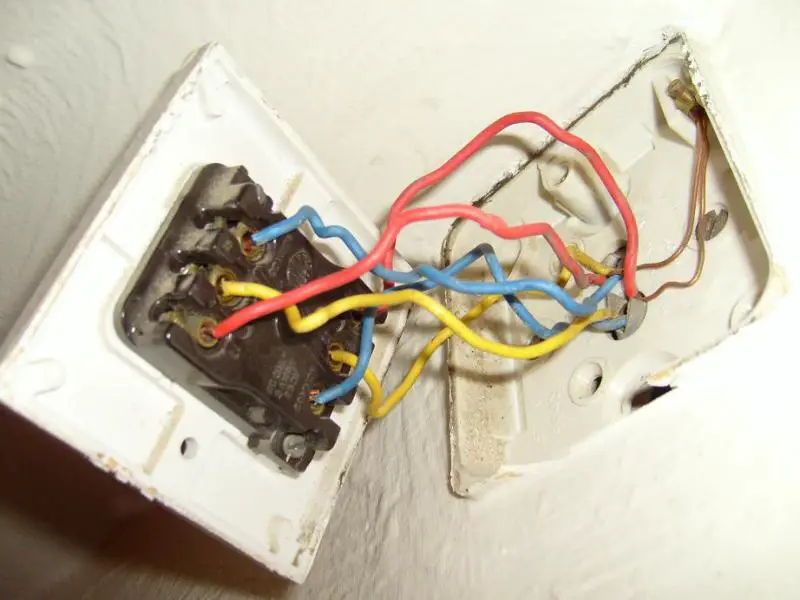
I can't work out what's going on. Photos of the wiring are attached. Is anyone able to suggest why it might be like this, and how I might go about putting it right?

Happy to buzz out wires if necessary to work out what's connected where.

Any advice much appreciated!

Thanks,
Mark

 
Sponsored Links
The problem is probably at a junction box or ceiling rose. But you may be able to cure it by swapping the red cable with the yellow or blue one at each switch.
 
There could be various problems, but a likely fix will be to swap the blue and red wires at the middle switches only.
 
have a good look in the 2 gang switch on the middle floor.

Do all the wires from one cable to go into one switch ?
 
Sponsored Links
if your line in the middle switch is in the right place, then your middle switch is wired wrong..

you want the red in com, yellow in L1 and blue in L2..

at the moment it looks like the blue is in the common..?

please post a clearer and larger picture of the middle switch.. we can't see detail on it..
 
Yep, on the middle switch can you also include a photo showing which cable the red/yellow/blue wires belong to?
 
Hi all,

Thanks for all the replies.

Do all the wires from one cable to go into one switch ?
Good question. No, they don't. Hadn't noticed that. Might go some way to explain why I couldn't make head nor tail of it all. I'll try to describe:
Cable 1: Red->RightL1. Yellow->LeftL1. Blue->RightC
Cable 2: Red->LeftL2. Yellow->RightL2. Blue->LeftC
(At the moment:
Right switch: does the light on level 2.
Left switch: does the light on level 4.)

Tried to get a better photo - it's not great, sorry, but I think it shows what I've described above.

I suspect if I just sort out the mix of wires between the two switches, things might come right. Maybe someone has a clue why they might be like that in the first place, though..? Is there some two-light, four-switch setup I don't know about?

 
It is a right muddle!
At least now you have a pic you can back track, personally first I'd try taking the red from one of the cables, connect this to COM. Connect the yellow and blue to the corresponding L1 and L2.
Do the same for the other cable, see if that works.
 
get some sleeving for those bare copper "earths"..

as advised..

for each cable, put the red into the C or Com..
the yellow into the corresponding L1..
the blue into the corresponding L2..
 
Thanks again for all the replies. I'm just about to try unravelling the middle floor switch as advised. One question though: the diagrams here (from this site) show the yellow as being the "common" and red and blue going to L1 and L2 (for non-harmonised colours anyway). Red as common seems to be the consensus here, but just wondering why the discrepancy..?
 
from what i see there is only one diagram on that page that uses yellow as the common.. and the picture above it clearly shows the right way to do it..

the diagrams and drawings on there are submitted by individuals, and as such are subject to that individuals preferred method of installation.. as is any installation you go to that you didn't do yourself..
 
If you click on the "click here for non-harmonised colours" links, all three diagrams have yellow as common... but not to worry :)

Thanks all - rewired the double switch to separate out the two circuits, and it now works beautifully. (Also put green/yellow sleeving on the earths and red sleeving on the yellows and blues.)

One job down, 99 to go...

Thanks again for the help - very much appreciated!
 
Does that switch with the wooden panelling behind it have a proper back box?
 
Does that switch with the wooden panelling behind it have a proper back box?
No :( No back box at all. Thanks for the reminder - I will put one in as it should be possible with not too much destruction of the wood.

It's not the worst bit of wiring in the house, by a long shot. My next concern is the two 2.5mm twin&earth cables which go to the (half removed) fish pond - they are buried under the soil for about 5 metres, apparently without any form of protection, and I haven't yet managed to work out what they're connected to. Presume they're live as the pump was running when I viewed the house.

As I said, some interesting wiring here..!
 

DIYnot Local

Staff member

If you need to find a tradesperson to get your job done, please try our local search below, or if you are doing it yourself you can find suppliers local to you.

Select the supplier or trade you require, enter your location to begin your search.


Are you a trade or supplier? You can create your listing free at DIYnot Local

 
Sponsored Links
Back
Top