Duplicate Electrics now in Wiki

Joined
27 Aug 2003
Messages
69,775
Reaction score
2,887
Location
London
Country
United Kingdom
) HALOGEN LAMP BASES

There are 2 common types of mains halogen lamp bases,GZ10 and GU10.

gu10bn6.jpg
gz10rv0.jpg


GZ10 lamps are the dichroic (cool beam) type, where a lot of heat comes out of the back, and GU10s have internal reflectors (the lamps are also known as PARxx - Parabolic Aluminium Reflector<size>) where the heat comes out forwards.

If you look you'll see that you can put a GU10 lamp in a GZ10 fitting, but not the other way around. This was done so that you couldn't put a dichroic lamp into a luminaire designed for PAR lamps, as the rearward-reflected heat would damage it.

Well guess what - people have now started making dichroic GU10s :rolleyes:

If a luminaire has a GU10 base, then unless the instructions explicitly say otherwise, you must only use PAR GU10s in it, not dichroic.
 
Sponsored Links
8 ) HOW TO JOIN CABLE

If you need to join a cable, and you can not use a junction box or choc blocks you should use a pair of Ratchet crimpers.

DVDHCR15.jpg


This pair of ratchet crimpers is available from here
 
9) CABLE INFO

Since people keep saying 'there is a 3 core' when it is twin and earth etc, this is a guide to what cable it is:

Twin and Earth (T+E)

This has 2 core carrying the load and an earth. This is NOT 3 core!

CA1G.jpg


3 Core and Earth (3C+E) (mostly known as 3 core)

This has 3 cores for carrying the load and an earth. Mostly used in 2 way lighting circuits and interlinking smoke alarms. Also used to power a fan, i.e permanent live, switched live and neutral.


CA1SLASH3G.jpg
 
10) BORROWED NEUTRALS and why they are a BAD THING

A borrowed neutral is where something (nearly always a light) has its live connection on one circuit and its neutral on another:


This is most commonly found with 2-way switching of a landing light. The live originates on the downstairs lighting circuit and goes through the downstairs and upstairs switches to the landing light, where of course a neutral is also needed, and the easiest place to get one is from the upstairs lighting circuit.

It was done like this for years, with never a problem because people only had 1 lighting circuit. The problem arises when the lighting is split into two - Upstairs & Downstairs.

The reason it's a problem is shown below. Consider the two circuits as before, and you want to break into Circuit 2 at point X to install a new light. So you switch off the MCB, or pull the fuse, verify that the circuit is dead, and cut the cable.
At that point some or all of the neutral cable in Circuit 2 becomes live via the path through the light from Circuit 1.
 
Sponsored Links
13 ) HOW DO I KNOW WHAT CABLE SIZE I HAVE?

1mm² CSA T&E has overall dimensions of 7.8mm x 4.25mm

1.5mm² CSA T&E has overall dimensions of 8.2mm x 5mm

2.5mm² CSA T&E has overall dimensions of 10.3mm x 6mm

4mm² CSA T&E has overall dimensions of 11.9mm x 6.25mm

6mm² CSA T&E has overall dimensions of 13.5mm x 7mm

10mm² CSAT&E has overall dimensions of 17.1mm x 10mm

16mm² CSA T&E has overall dimensions of 19.4mm x 10mm

Source: http://www.tlc-direct.co.uk

p3034590_l.jpg
 
14) CABLE PROTECTION

A few people posting are saying they are going to put cable inside PVC conduit - thus offering "protection" to the cable.

The fact is PVC conduit offers very little mechanical protection. Hit it with a hammer: it will shatter. Hit it with a spade: it will go straight through, and someone may get a shock.

Do not bury twin and earth cable in PVC conduit, no matter how much cement you apply to the ends - water will get in and someone will put their shovel through it. PVC conduit is only really used to shield cables from the sun's damaging UV light, to provide junction points, and sometimes for aesthetic reasons.

Methods of mechanical protection for cables:

1. SWA (Steel Wire Armour) cable.

This is by far the easiest option. This has steel wires running along the outside of the current-carrying cores. These steel wires are earthed at at least one end of the cable so if someone shoves a spade through it, the spade will conduct very high current from the live cores to the earthed armour and trip the circuit breaker almost immediately.

It is also far better protected against impact. The ends of the cable are terminated in special glands in order to earth the steel sheath properly.

SWA Cable:

Click image to enlarge
SWA Glands:

Click image to enlarge
2. Earthed metal conduit.

This provides similar protection to SWA as it encloses the cable in an earthed metal layer. It is tougher than SWA, so you are less likely to put your spade through this!

Much more difficult for DIYers to install - the ends need threads cutting and special tools are needed for this. It is also more expensive, especially when you've bought all the tools.

Very rarely used to run underground installs. Most often used for industrial and commercial installs or in domestics where protection is required eg. garages, and run along walls outside.
 
15 ) FIRE HOODS

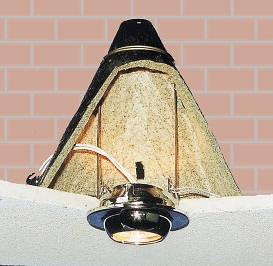
FHDC150.JPG


These are used to maintain the fire rating of a ceiling. When a fire occurs, the heat causes the intumescent material which lines the hood to expand and fill the void between the lamp and the hood. This seals any gap in the ceiling and therefore maintains the fire rating of the ceiling.

These hoods are not required in most domestic house situations. If the ceiling is in a flat and there is another flat above you, you must use fire hoods. If for some bizarre reason you are fitting halogens in a garage with a habitable room above, you must also use these hoods. As far as i know, these are the only COMMON circumstances which require the maintenance of fire rating of ceilings in domestic situations.

Where fire rating is not required, and you simply need to keep insulation at bay, an MDF box, clay flowerpot, or any sort of enclosure you can make yourself from relatively heat-proof material, will be cheaper and allow the lamps to dissipate heat better than a fire hood.

Suggested sizes are 6-10 inches square and 8-12 inches high. Some say you should drill a couple of holes in the top for heat dissipation (hence the flowerpot suggestion!).
 
16) FITTING A DIMMER SWITCH

Step 1

Select the switch you wish to replace.


Click image to enlarge

Step 2

Switch of the electricity at the consumer unit.


Click image to enlarge

Step 3

Unscrew the existing switch from the wall, and gently pull the switch forwards taking care not to damage any of the wires.


Click image to enlarge

Step 4

Test the wiring at the switch with a multimeter or approved test lamp, to ensure the correct circuit has been isolated, and no power still remains at the switch.

DO NOT use neon screwdriver or volt stick type testers for this, as they are not reliable or accurate.


Click image to enlarge

Step 5

If you discover a black switched live then this should have a piece of red sleeving or tape fitted to it, to prevent confusion between switched lives and neutrals.


Click image to enlarge

Step 6

Carefully note which wire connects to which terminal on the existing switch and mark each wire separately. Unscrew all the terminal screws, and remove the old switch.


Click image to enlarge

Step 7

Connect each wire to the corresponding terminal on the dimmer switch.
If the terminals are labeled differently on the dimmer from the old switch, then have a look in the Wiki for common switch labels.


Click image to enlarge

Step 8

If you are fitting a metal dimmer (brass, chrome etc) then you need to earth the switch plate.
If an earth lead is pre-attached to your dimmer then connect it to the existing earth wire in the terminal in the back box.
If no link is fitted then you need to install one yourself. You can do this with a scrap of earth wire, and some earth sleeving.


Click image to enlarge


Step 9

If your metal back box has top and bottom screw lugs then you may need to flatten these to allow the switch to fit in the back box properly.
This can be done by carefully tapping a screwdriver with a hammer to bend the lug flat with the wall of the back box.


Click image to enlarge

Step 10

If your wall has recently been plastered or painted then you must fit the supplied plastic gasket between the wall and the switch plate to prevent and damp in the wall from tarnising the finish of the switch plate.


Click image to enlarge

Step 11

Carefully screw the new switch to the back box taking extreme care not to trap any wires. Be careful as the switch fixing screws can trap wires when the switch is screwed into place.
Use a spirit level to make sure the switch is on straight.


Click image to enlarge

Step 12

Switch the power back on at the consumer unit and test.
 
17 ) CHANGING A CONSUMER UNIT

p2639740_l.jpg


If you need to add a consumer unit, or change the existing one, the best course of action would be to call the Regional Electricity Company (REC), and ask them to fit (or install one yourself and ask them to wire in) an isolator.

This is fitted in between the tails from the meter and the CU itself which means that the tails to your CU are also isolated thus making the CU absolutely safe to work on once the isolator is open.

If you want to, you can always fit a Henley block in between the new isolator switch and the CU, allowing you to fit extra CU's in the future.

PLEASE DON'T tamper with the cut-out seal or cut out or tamper with meter seal or tails.

This will render you liable to prosecution, and may even be lethal. One slip is all it takes - I'm not trying to scare anyone, but I've seen it done, and it's not pretty.

Leave the meter seals, cut out etc to the REC, and once you (or they) have installed your isolator you can work on the system in complete safety without bothering the REC again.


======A============B=========C=======D=======E

=: cable
A: cutout
B: meter
C: isolator
D: Optional Henley Block
E: CU or CU's.
 
) USEFUL REFERENCE BOOKS Thanks to Ban ALL Sheds

IMPORTANT NOTE - when buying books from Amazon, seek confirmation that they are the latest versions.


419EM1MST6L._SL500_AA240_.jpg
http://www.amazon.co.uk/exec/obidos/ASIN/0852028172

510LkaElnZL._SL500_AA240_.jpg
http://www.amazon.co.uk/Collins-Complete-Wiring-Lighting-Jackson/dp/0007267282

51Z4HMH6K8L._BO2,204,203,200_PIsitb-sticker-arrow-click,TopRight,35,-76_AA240_SH20_OU02_.jpg
http://www.amazon.co.uk/Readers-Digest-Wiring-Lighting-Manual/dp/027644079X


No idea about this one, but if it's as good as their car manuals it'll be very useful, given the description, as it's bang up-to-date:

51H7KT7Q6DL._SL500_AA240_.jpg
http://www.amazon.co.uk/Home-Electrics-Manual-Step-step/dp/184425240X


. . . . .
anblulin.gif


The next 2 are essential.


414I7RjVdwL._SL500_AA240_.jpg
http://www.amazon.co.uk/exec/obidos/ASIN/0863418546

41hj3o997nL._SL500_AA240_.jpg
http://www.amazon.co.uk/exec/obidos/ASIN/0863418627 or http://www.theiet.org/publishing/books/wir-reg/electricians-guide-part-p-2nd-edition.cfm


As is a guide to the Wiring Regulations, such as this

41OwCK9EwCL._SL500_AA240_.jpg
http://www.amazon.co.uk/exec/obidos/ASIN/0953788555 or http://www.tlc-direct.co.uk/Products/TLGUIDE.html

Or one of Brian Scaddan's many books.

You can get a feel for the 16th Edition version of Whitfields book here.


. . . . .
anblulin.gif


The next three are pretty handy guides, the Amicus ones being small enough to fit in your toolbox.:


51y0QieDxiL._BO2,204,203,200_PIsitb-sticker-arrow-click,TopRight,35,-76_AA240_SH20_OU02_.jpg
http://www.amazon.co.uk/Part-Doctor...=sr_1_1?ie=UTF8&s=books&qid=1266839031&sr=1-1

electricians-guide-to-good.gif
http://www.technicaltrainingsolutions.co.uk/publications.shtml

front-cover-elec-guide-insp.gif
http://www.technicaltrainingsolutions.co.uk/publications.shtml


. . . . .
anblulin.gif


I would strongly recommend a copy of the Wiring Regulations, and also (but not as strongly) copies of the Guidance Notes, but bear in mind there were new versions out in 2008 onwards, as the Wiring Regulations were revised. A lot of people on eBay are still selling old versions, pay close attention, and don't buy the 16th Edition ones by mistake.


31VCIsGDpBL._SL500_AA240_.jpg
http://www.amazon.co.uk/exec/obidos/ASIN/0863418449 or http://www.theiet.org/publishing/books/wir-reg/17th-edition.cfm


31sgoOfkmYL._SL500_AA240_.jpg
http://www.amazon.co.uk/exec/obidos/ASIN/0863418554

41n5xWMi7hL._SL500_AA240_.jpg
http://www.amazon.co.uk/exec/obidos/ASIN/0863418562

31yVJuW-gLL._SL500_AA240_.jpg
http://www.amazon.co.uk/exec/obidos/ASIN/0863418570 or http://www.theiet.org/publishing/books/wir-reg/inspection-testing-5th-edition.cfm

41gWiXreymL._SL500_AA240_.jpg
http://www.amazon.co.uk/exec/obidos/ASIN/0863418589

41FMYZ7Z9JL._SL500_AA240_.jpg
http://www.amazon.co.uk/exec/obidos/ASIN/0852969937

41Q60enNjRL._SL500_AA240_.jpg
http://www.amazon.co.uk/exec/obidos/ASIN/0863418600

41zedVbBaML._SL500_AA240_.jpg
http://www.amazon.co.uk/exec/obidos/ASIN/0863418619

41muWKrAWCL._SL500_AA240_.jpg
http://www.amazon.co.uk/exec/obidos/ASIN/0863416160


31NSrju2i6L._SL500_AA240_.jpg
http://www.amazon.co.uk/Electrical-Installation-Design-Guide-Calculations/dp/0863415504 or http://www.theiet.org/publishing/books/wir-reg/electrical-installation-design-guide.cfm


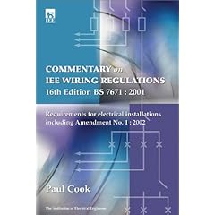
The Electrician's Guide shown above is a good explanation of the regs, but if you fancy one with a bit more of the electrical engineering theory behind it all, I can recommend this:

41RPQJ53PNL._SL500_AA240_.jpg
http://www.amazon.co.uk/exec/obidos/ASIN/0852962371 or http://www.theiet.org/publishing/books/wir-reg/19253.cfm

It is a commentary on the 16th, not the 17th, and the new one will be out soon, but if you can find a cheap second hand copy it will still be useful and informative, as the underlying theory never changes.
 
) Online Sources of Reference Materials Thanks to Ban all sheds

Electricians Guide: here

TLC Cable Calculator: here

Kevin Boone's Cable Selection Guide: here NOW HERE: http://web.archive.org/web/20070327014113/http://www.kevinboone.com/cableselection_web.pdf[/b]


Kevin Boone's useful basic guides:

http://www.kevinboone.com/electricity.html NOW http://web.archive.org/web/20080118063245/www.kevinboone.com/PF_electricity.html[/b]

http://www.kevinboone.com/domesticinstallations.html NOW http://web.archive.org/web/20071013043715/www.kevinboone.com/PF_domesticinstallations.html[/b]

(Disclaimer - I am not Kevin Boone, nor am I in love with him - I just found his site one time and thought it was pretty useful).

Bonding Plastic Pipes: here

Info on RCDs:
http://en.wikipedia.org/wiki/Residual-current_device
http://www.westernautomation.com/pages/demystify.htm
http://www.memonline.com/guide06.html
 
) MCBs Thanks to Ban all Sheds

Reason says that there ought to be a Type A MCB, but I've never seen any info on one.

B, C, and D have different time/current curves for tripping. Type B will trip faster than type C for a given over current, and type C will be faster than type D. The other way of looking at it is that type Ds need more current than type Cs, which need more than type Bs, to trip in a given amount of time.

In summary: [code:1]Type Will not trip in Will trip in
100ms at rating 100ms at rating

B 3 x 5 x
C 5 x 10 x
D 10 x 20 x [/code:1]

This chart shows different curves superimposed:

mcbs.jpg


Why does this matter?

One of the jobs of a protective device is to disconnect the supply in the event of an earth fault - i.e. if something goes wrong with your fan heater or toaster and a live conductor makes contact with the earthed case, then a current will flow to earth. What we need is for that current to get large enough for the fuse to blow or the MCB to trip.
The situation of current happily flowing to earth without tripping the breaker, and therefore with the case of the toaster remaining live is a Bad Thing.

We also want the current to get large enough quickly so that the case doesn't remain live for very long, and the earth conductor doesn't have time to get hot enough to melt. This is called the disconnection time, and clearly, as I=V/R, we need a low resistance to get a high current. A C type breaker needs a higher I to trip quickly than a type B does, so a circuit protected by a type C needs a lower earth loop resistance than one protected by a type B.

How much lower depends on how fast you want it to disconnect. The wiring regs say that a socket circuit should have a disconnect time of 400ms.
Lighting circuits, by contrast, require a 5s disconnect time,and there is a case to be made for using type C breakers on lighting circuits because they are much less prone to tripping with the brief current surge that occurs when a lamp fails than a type B is.

At 5 seconds the curves for type B and C breakers have almost met, e.g. there is very little difference in the earth loop resistance limits for a circuit with that disconnection time.

Not so at 400ms though. The typical maximum values, in ohms, for the earth loop resistance (Zs), for 32A type B and C MCBs are:

[code:1]Type 0.4s 5s

B 1.50 1.71
C 0.75 1.6[/code:1]

As you have a TN-C-S supply, you might get away with type Cs on socket circuits, as the maximum allowable external component of the earth loop impedance (Ze) for that type of supply is 0.35 ohms. (And of course the DNOs strive ceaselessly to ensure that this limit is never breached. :cool: )

For a TN-S supply, Ze is allowed to be 0.8 ohms, so type C breakers are flat-out not allowed for socket circuits, but even with TN-C-S, you can see that there's not much left for your R1+R2 (the combined resistance of the live and earth wires in a circuit).

With a TT supply, Ze could be very high, which is why RCD protection is mandated in the regulations.

That, briefly is why you'll see people expressing concerns about earth-fault-loop impedance's.
 
) SIZING MCBs & CABLES Ban all Sheds

Note - this considers overload protection only. Other factors such as voltage drop and disconnection times need to be considered when designing a circuit. Also, it only quotes the example tripping/non-tripping currents for Type B MCBs, not cartridge or rewirable fuses, which are not the same.

More detail on these aspects, and factors which affect a cable's capacity can be found here.

Protective devices have 3 values of interest here:

In: its nominal rating (e.g. 32A)
I1: its non-fusing/non-tripping current. For a Type B MCB this is 1.13In
I2: its fusing/tripping current. For a Type B MCB this is 1.45In, and it must trip within 1 hour

So if we have a circuit whose design current (i.e. the current that it is expected to carry in normal use) is Ib, then this should not be greater than the rating of the protective device:

Ib <= In

If Iz is the current-carrying capacity of the cable for continuous service allowing for the way that it has been installed, then this must be no less than the rating of the device:

In <= Iz

Finally, 1.45 times the current carrying capacity Iz of the cable must be no less than I2, the current causing effective operation of the device:

1.45Iz >= I2

So Ib <= In <= Iz

and

I2 <= 1.45Iz.

Or if you prefer pictures:


Click image to enlarge

Running an MCB at or near its limit for long periods will cause it to overheat, and eventually weaken. But you shouldn't do that - look at the diagram, Ib is lower than all
 
11) EARTHING ARRANGEMENTS Thanks to Lectrician

There are 3 main commonly used Earthing Arrangements found in domestic installations.

TN-C-S ; TN-S ; TT

The T stands for 'TERRA' which is French for Earth.
The C stands for 'COMBINED' in relation to the neutral and the earth.
The S stands for 'SEPARATE' in relation to the neutral and the earth.
pinkscorevq3.gif

TN-C-S

A TN-C-S system has the neutral and earth COMBINED in the DNO's supply cable(s), and SEPARATE
within the installation, (this being the meter position and onwards).


Click image to enlarge
pinkscorevq3.gif

TN-S

A TN-S system has the neutral and earth SEPARATE throughout the entire system, including the DNO's Supply cable(s).


Click image to enlarge

OR


Click image to enlarge

OR


Click image to enlarge
pinkscorevq3.gif

TT

A TT system has the neutral running in the supply cable(s) as normal, and the earth from the installation
is connected to an appropriate Earth Electrode inserted into the ground.
An RCD is essential in an installation formed by a TT earthing arrangement.


Click image to enlarge
pinkscorevq3.gif

It is the DNO's responsibility to provide a TN-C-S or a TN-S supply, if requested and available,
it is not their responsibility to provide a TT earthing arrangement.

In order for the DNO's to provide a TN-C-S supply, they have to construct their network to the
standards of PME (protective multiple earthing), this is why a TN-C-S system is often referred to as a PME installation.
 

DIYnot Local

Staff member

If you need to find a tradesperson to get your job done, please try our local search below, or if you are doing it yourself you can find suppliers local to you.

Select the supplier or trade you require, enter your location to begin your search.


Are you a trade or supplier? You can create your listing free at DIYnot Local

 
Sponsored Links
Back
Top