Hi, I'm sure this should be simple but I cannot get my head around it and Googleing just compounds my confusion!
My brother bought me a 'simple' solar kit for lighting my small shed but no instructions came with any of the parts. As pictured here there is a panel, an 'ecoworthy' solar charge controller, a 3 gang switch panel, two LED strip lights and a bunch of spade connectors:

Everything is relatively self-explanatory to me as the solar charge controller shows where the connections go:

However, the 3 gang switch panel has royally confused me as I haven't worked with DC electrics before and pictures of similar panels look like a bunch of spaghetti! The front looks like this:

and the rear looks like this:

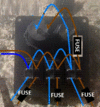
In my mind there is positive and negative going from the 'load' connection of the solar controller to the panel. However, what specifically are they connecting to on the back of the panel?
The cigarette lighter and USB have clearly marked positive/negative connections. Each of the three switches have four connections but not marked with anything. I'm presuming one half of the switch connectors will be inputs from the other connectors in some daisy chain fashion (from images of similar yet not exactly the same panels!) and the other half will be postive/negative going to the two LED lights i.e. two of the switches. No markings means I don't know where to start
Can anyone help with how the panel should be wired, or at least the methodology I should be following? The other thing I'm seeing whilst googling is fuses (which are missing from this kit)...should I have them for this particular two led strip light setup and whereabouts would they go?
Thanks
Dan
My brother bought me a 'simple' solar kit for lighting my small shed but no instructions came with any of the parts. As pictured here there is a panel, an 'ecoworthy' solar charge controller, a 3 gang switch panel, two LED strip lights and a bunch of spade connectors:
Everything is relatively self-explanatory to me as the solar charge controller shows where the connections go:
However, the 3 gang switch panel has royally confused me as I haven't worked with DC electrics before and pictures of similar panels look like a bunch of spaghetti! The front looks like this:
and the rear looks like this:
In my mind there is positive and negative going from the 'load' connection of the solar controller to the panel. However, what specifically are they connecting to on the back of the panel?
The cigarette lighter and USB have clearly marked positive/negative connections. Each of the three switches have four connections but not marked with anything. I'm presuming one half of the switch connectors will be inputs from the other connectors in some daisy chain fashion (from images of similar yet not exactly the same panels!) and the other half will be postive/negative going to the two LED lights i.e. two of the switches. No markings means I don't know where to start
Can anyone help with how the panel should be wired, or at least the methodology I should be following? The other thing I'm seeing whilst googling is fuses (which are missing from this kit)...should I have them for this particular two led strip light setup and whereabouts would they go?
Thanks
Dan


