Honeywell cm927 and bdr91 change to Drayton RF902 (1)

Joined
25 Sep 2024
Messages
5
Reaction score
0
Country
United Kingdom
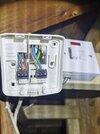
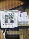
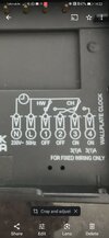
Hi all, my Honeywell CM927 RF system has blanked three years running I've done the fixes but now going to change over to a Drayton RF system.
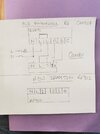
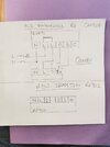
The neutral live live wiring of the Honeywell system does not correspond to the new Drayton system,can you offer me a wiring solution please?
 

Attachments

  • IMG_20240925_105835.jpg
    IMG_20240925_105835.jpg
    148.2 KB · Views: 18
  • IMG_20240918_102204.jpg
    IMG_20240918_102204.jpg
    177.4 KB · Views: 19
Last edited:
Sponsored Links
Hi all, my Honeywell CM927 RF system has blanked three years running I've done the fixes but now going to change over to a Drayton Rf902 system.
The neutral live live wiring of the Honeywell system does not correspond to the new Drayton system,can you offer me a wiring solution please?
 

Attachments

  • IMG_20240925_105835.jpg
    IMG_20240925_105835.jpg
    148.2 KB · Views: 28
  • IMG_20240918_102204.jpg
    IMG_20240918_102204.jpg
    177.4 KB · Views: 27
The RF902 is a dual channel programmer, controling heating and hot water - it provides mains voltage to its output terminals.
Your existing controller has a single channel for heating only.
It has 'volt free contacts', meaning it's compatible with the (extra) low voltage circuits in some boilers.

I believe the Drayton RF901 is the equivalent single channel controller, although it may still be possible to use the RF902, depending on your boiler.
 
excellent it's obvious you know just what you're talking about!
if I swapped it for an RF 901 what would the wiring layout look like compared to what I have then please
 
Sponsored Links
it's obvious you know just what you're talking about!
I wouldn't say that! ;)

if I swapped it for an RF 901 what would the wiring layout look like compared to what I have then please
Screenshot_20240925-140315_Adobe Acrobat.jpg

The two Blue wires in N on CM927 to N on RF901
The two Brown wires in L to L - forget about the small link wire - that wasn't even needed on the CM927.
Brown wire in A to terminal 1
Blue wire in B to terminal 3
The Green/Yellow earth wires can be connected together in the RF901s earth terminal.

The L and N wires could also be tidied up a little, there's a few too many straggly ends of copper showing at the moment!
 
I thought so too regarding the strayly ends and the possibility of Earth leak or shorting.
I'll send you a photo of the Finished product and I hope you'll be proud.
So I think this will be the last question if I just held on to the 902 could I do the 1 and 3 and leave the 2 and 4?
Chris.
 

Attachments

  • Screenshot_20240925_142240_com.google.android.apps.photos.jpg
    Screenshot_20240925_142240_com.google.android.apps.photos.jpg
    130.7 KB · Views: 9
just held on to the 902 could I do the 1 and 3 and leave the 2 and 4?
No, as earlier, the 902 outputs mains voltage.
Without knowing your boiler, or how it's wired up, that may be a costly mistake - i.e. if you had a Vokera boiler, the control circuit is 24V DC, and you'd be paying for a new boiler PCB!
If your boiler was operating with a mains voltage control circuit, we would have to discover which wire (currently in A, or B) is the live return to the boiler.
It would be this wire that went into terminal 4 of the 902 - terminals 1,2 &3 would be unused.
You'd also have a hot water control showing, that had no function - just a little annoying!
 
Excellent information.
you certainly relay a good message and I thank you very very much for your assistance.
I shall get the 901 and wire up
 

DIYnot Local

Staff member

If you need to find a tradesperson to get your job done, please try our local search below, or if you are doing it yourself you can find suppliers local to you.

Select the supplier or trade you require, enter your location to begin your search.


Are you a trade or supplier? You can create your listing free at DIYnot Local

 
Sponsored Links
Back
Top