- Joined
- 8 Jul 2024
- Messages
- 5
- Reaction score
- 0
- Country

Hello All,
Just wanted to get some feedback on a system design I came up with.
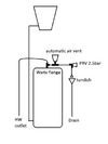
I understand that in a vented system the water in the tank should remain below 20 degrees to prevent legionella but it never made sense why you would route the hot water vent pipe back into the tank. I took inspiration from unvented systems to avoid that flaw. My main concern would be the cylinder not being built to withstand 2-3 bar pressure (still trying to find a sub 2 bar prv) but I figured that actually any increase in pressure would just force water to expand back up the water inlet and any excess would go in the tank over flow. Does this design make sense or is it over engineered for something that isn't really a problem?
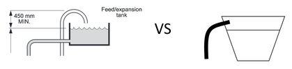
Another question I have is why do vented systems have a goose neck going over the top into the tank and not just have the pipe at a near 90degrees with a gentle rise? Wouldn't that help vent air better and avoid wasting extra length of pipe? Surely as long as the exit is above the water line and the over flow there shouldn't be any issues?
Thanks for any feedback,
Glnovice90
Just wanted to get some feedback on a system design I came up with.
I understand that in a vented system the water in the tank should remain below 20 degrees to prevent legionella but it never made sense why you would route the hot water vent pipe back into the tank. I took inspiration from unvented systems to avoid that flaw. My main concern would be the cylinder not being built to withstand 2-3 bar pressure (still trying to find a sub 2 bar prv) but I figured that actually any increase in pressure would just force water to expand back up the water inlet and any excess would go in the tank over flow. Does this design make sense or is it over engineered for something that isn't really a problem?
Another question I have is why do vented systems have a goose neck going over the top into the tank and not just have the pipe at a near 90degrees with a gentle rise? Wouldn't that help vent air better and avoid wasting extra length of pipe? Surely as long as the exit is above the water line and the over flow there shouldn't be any issues?
Thanks for any feedback,
Glnovice90