I was fitting an extractor fan and found this...

WCA

Joined
31 Dec 2011
Messages
7
Reaction score
0
Country
United Kingdom
I was planning on fitting an extractor fan into the bathroom. This would be switched on and off by changing the single light switch outside the bathroom into a double switch and then running the wiring up into the attic. The light switch and extractor switch would be independent of each other, just sharing the same box.

I took the front off the light switch and discovered more than I expected. It appeared to have all the wiring in place to be a double switch. I went into the attic and traced the wiring to discover there already was an extractor fan, it was just hidden behind the tiles.

I though this would make my job easier as I could simply cut the wires to the old fan and connect the new fan which I did successfully. The problem came at the switch end as I cannot tell which wires coming out of the wall are connected to which wires in the attic.

//media.diynot.com/181000_180505_41020_18438592_thumb.jpg

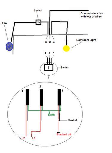
This diagram shows how it is wired at the moment. In this situation the light switch works fine. I have replaced the single switch with a double switch and if I wire it up the same, the light still works which is good.

What I need to know is which wires I need to connect to the L1, L2 and COM for the second switch to operate the fan. I am guessing I will need to run a wire between the two switches too.

In Summary - The picture shows what I have at the moment. I want to replace the single switch with a double switch with the two switches to work independently of each other.

Advice please.
 
Sponsored Links
Does the extractor have an overrun on it?
It would be difficult to suggest what wires should be connected where until you have proved they are actually fit to use, ie have continuity between switch and fan and the insulation resistance is within permitted value.
Do you have means for testing this?
 
Determine which of the two reds from cables 1 and 2 is live ALL THE TIME - known as permanent live. Put this in one of the common terminal terminals. Put a short link of red wire from this terminal to the other common.

EDIT; I APPEAR TO HAVE ACCIDENTLY DELETED MOST OF MY REPLY HERE TRYING TO SEND A QUOTE. Don't imagine I can get it back now. Don't suppose it matters since the op seems to have got it working.
 
I do not have any special tools to check the state of the wiring. It is grey cable containing quite thick black, red and unsheathed earth. All three cables in the attic appear undamaged with no cracks or obvious deterioration.

I have disconnected the old fan and actually wired in a lamp so I can easily tell if there is power reaching the wires where the new fan will be. I was going to use this to test if the circuit works.

With the new switch wired in exactly as the old one was, the left switch on the new 2 switch unit works fine for the bathroom light.

Can you suggest what the correct wiring would be assuming we new which wires were which and then I can play guess the wire.

At the moment I am not certain what the correct wiring would be as all examples I can Google only have two sets of red, black and earth while I am faced with three.

My deduction so far is:

the red wire not connected to anything goes to the fan.
One of the connected reds goes to the bathroom light.
The other connected red goes to the rest of the lighting circuit.

If that is true we can then identify the equivalent blacks and earths.

It would be useful to know which of the connected reds was which it would be good. Is this essential though?
 
Sponsored Links
Sparkwright - I think you have correctly interpreted the situation. The extra switch in the attic appears redundant. The wires from this disappear down into the outside wall and when I look outside there is a vent which I assume is the old fan.

You are right about the different switches having different labels btw.

SO, from your instructions I think I need to do this:

Leave the existing wires for the bathroom light in COM and L1 on switch 1
Connect the blanked off red to L1 on switch 2
Connect a bit of wire between COM on switch 1 and COM on switch 2

If this doesn't work then switch COM and L1 on switch 1 as they were the other way round to what I expected.

Here's hoping...

You got it.

If the new switch has com, L1 and L2 you should only need to use the com and L1 connections.

In the unlikely event the switches appear to work upside down, you would use com and L2. Nowadays it's nearly always com and L1 for simple 1 way operation.
 
But for safety reason you need to confirm continuity and insulation resistances, you would be a fool not to.
I don't have to spell out the dangers of an unsafe circuit being used in a bathroom do I or any room for that matter?
Also you will need RCD protection on this circuit.
There also legal requirements that are involved if you are altering circuits within this location, this may not apply to you but do make yourself aware of them!
//www.diynot.com/wiki/electrics:part_p
//www.diynot.com/wiki/electrics:building_warrants
 
prenticeboy - I agreed about the safety side even though the whole circuitry is outside of the bathroom but how do I 'confirm continuity and insulation resistances'?
 
prenticeboy - I agreed about the safety side even though the whole circuitry is outside of the bathroom but how do I 'confirm continuity and insulation resistances'?
You need a multimeter to test continuity and you need a IR tester to test for insulation resistance. The multimeter can be bought quite cheaply this will also allow you to test for voltage. Insulation resistant tester are more expensive but can be hired.
A guide for testing http://www.tlc-direct.co.uk/Book/8.1.1.htm
this is a little dated as the recommend Ω value for low voltage at 230V is 1MΩ or greater and not 0.5MΩ at 500V DC.
I don't want to sound patronising but if you have no experience of testing, I would employ someone who does.
Just because the circuit and appliance/equipment on it works, does by no means makes it safe.
 
Wow - that was frustrating but it works now.

I wired the switch up as suggested.

Flicked the fan switch on. nothing.
Flicked the fan switch off. nothing.
Flicked the light switch on. Light on.
Flicked the fan switch on. nothing.
Flicked the fan switch off. nothing.
Flicked the light switch off. Light off.

I replaced the fan with a lamp so that I knew the problem wasn't with the fan and I could see it light up easily.

Flicked the fan switch on. nothing.
Flicked the fan switch off. nothing.
Flicked the light switch on. Light on.
Flicked the fan switch on. nothing.
Flicked the fan switch off. nothing.
Flicked the light switch off. Light off.

I removed the extra switch from the circuit and in doing so spotted that it had a blown fuse. Hah hah, I had found the problem!

Flicked the fan switch on. nothing.
Flicked the fan switch off. nothing.
Flicked the light switch on. Light on.
Flicked the fan switch on. nothing.
Flicked the fan switch off. nothing.
Flicked the light switch off. Light off.

I swore loudly and asked no one in particular why the b*****y lamp wouldn't work. My wife took the lamp from me before I threw it through the roof, plugged it in and told me the bulb had blown. We replaced the bulb with a working one.

Flicked the fan switch on. nothing.
Flicked the fan switch off. nothing.
Flicked the light switch on. Light on.
Flicked the fan switch on. The fan actually started!!!
Flicked the fan switch off. The fan stopped.
Flicked the light switch off. Light off.

I went back to the switch and swapped the two wires that were in the original switch so the one in COM was now in L1 and visa versa.

Flicked the fan switch on. Fan on.
Flicked the fan switch off. Fan off.
Flicked the light switch on. Light on.
Flicked the fan switch on. Fan on.
Flicked the fan switch off. Fan off.
Flicked the light switch off. Light off.

3 hours after I originally connected everything up correctly (apart from the last switching of wires) I actually have a working fan and light.

Every other problem I had was just put there so you guys can smile at me and know that your jobs are safe.

Thanks for all the help and advice. I will be getting this checked by a sparky in the New Year.

Hapopy New Year to everyone and I hope you have a great time.
 
I don't know why one bothers about advising on safety.
prenticeboy - I agreed about the safety side
In that case I assume if you care enough about your family, pets, property, neighbours etc.. that you have now isolated this circuit until it has been correctly inspected and tested?

or maybe not, sleep well pal, hope you get to the New year!
 
  • Thanks
Reactions: WCA
Determine which of the two reds from cables 1 and 2 is live ALL THE TIME - known as permanent live. Put this in one of the common terminal terminals. Put a short link of red wire from this terminal to the other common.
 
  • Thanks
Reactions: WCA
Circuit is isolated but all in place now.

It was the fact the fan only worked when I had the light on that let me determine the wires were the wrong way round. I didn't know of another way of doing it except using the touch it and hope method which I decided not to try ;)

Thanks again for the help and happy New Year
 
I didn't know of another way of doing it except using the touch it and hope method which I decided not to try
Well - how about taking the trouble to actually learn how things work before you start fiddling with them, and equipping yourself with the necessary tools?

In summary - how about becoming competent to do electrical work?
 

DIYnot Local

Staff member

If you need to find a tradesperson to get your job done, please try our local search below, or if you are doing it yourself you can find suppliers local to you.

Select the supplier or trade you require, enter your location to begin your search.


Are you a trade or supplier? You can create your listing free at DIYnot Local

 
Sponsored Links
Back
Top