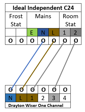
Good question! One of the 'Room Stat' connections will be a 'live' and the other the 'switched live'. But which is which?
The two diagrams on the same page of the Ideal Independent manual are contradictory. Looking at the terminal where the thermostat 'common' (which should be the live) is shown connected. The top diagram indicates below indicates that it's the terminal next to the L, but the diagram below that indicates that it's the end terminal. From memory, I think that the top diagram may be correct but can't be 100% certain.
If you have a multimeter and can test the terminals then it's easy. With no wires in either of the terminals and power on to the boiler, one will be live, the other won't. The one that isn't live is the 'switched live'.
Once you have determined which is which:
The N and L 230V supply is straightforward
Link L and Com (1) as shown by the dashed line in the diagram
'On' terminal (3) goes to the 'switched live' terminal at the boiler
Or:
If you don't have a multimeter the easiest way is to use a 4 core cable, again the N and L 230V supply is straightforward. Then the two terminals marked 'Room stat' go to the wiser terminals (1) and (3) in this case it doesn't matter which way around they go.
But this time don't make the link between (L) and (1)
With many Ideal boilers, it's necessary to open up a room sealed compartment to access the wiring terminals. if this is the case with yours, it's not a DIY job and should only be done by a RGI who can make the necessary safety checks to make sure that it's properly sealed up again afterwards.


