LED Driver - CPC wire and Voltage

Joined
30 Mar 2015
Messages
4,153
Reaction score
64
Country
United Kingdom
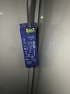
I’ve got a twin and earth mains cable providing input into an LED driver. The driver sits on top of a kitchen unit and I then have a 3 core flex that goes behind and down the kitchen unit into a JB that is screwed to the bottom of the unit. The 3M LED tape is connected and powered from this JB.

My questions:

1. The driver only has terminals for L and N. How should the CPC be terminated on both ends?

2. When using my 2 pole tester on the 12v terminals of the driver, it detects power when the circuit is energised but when I denergise it, the tester continues to report 12v and very slowly goes down in voltage. Whereas the mains terminals are either on or off depending on whether the circuit is energised. What’s the cause of this?

Thanks in advance.
 

Attachments

  • C27B21B1-3423-4DA3-B613-2DA997F8F5E9.jpeg
    C27B21B1-3423-4DA3-B613-2DA997F8F5E9.jpeg
    111.1 KB · Views: 116
Sponsored Links
2. When using my 2 pole tester on the 12v terminals of the driver, it detects power when the circuit is energised but when I denergise it, the tester continues to report 12v and very slowly goes down in voltage. Whereas the mains terminals are either on or off depending on whether the circuit is energised. What’s the cause of this?
This is totally normal.
The 'driver' contains capacitors that smooth the output voltage to 12V DC.
The capacitors in SMPS can be quite small and don't hold much charge - with the load connected, the charge may dissipate quickly - the LED's may fade to off, almost instantly.
Your 2 pole tester has high impedance - the charge wont dissipate quickly through the tester, and the voltage reading will decrease very slowly!

Edit:
For example:
The resistance of a 3m 12V 4.8W/m LED strip would be 10 Ohms.
Whereas the impedance of a typical DMM may be around 10 MOhm!

 
Last edited:
1. The twin and earth should be earthed at its origin. At the driver end the CPC should be sleeved and not connected.
 
Sponsored Links
The 230volt terminals on the driver are missing the required cover. This must be screwed in place

Hopefully you remember that the whole of the cable sheath must enter the enclosure?
. The cover also provides a clamp (strain relief) for the cable.
 
The 230volt terminals on the driver are missing the required cover. This must be screwed in place

Hopefully you remember that the whole of the cable sheath must enter the enclosure?
. The cover also provides a clamp (strain relief) for the cable.
All done. That was for the picture
 

DIYnot Local

Staff member

If you need to find a tradesperson to get your job done, please try our local search below, or if you are doing it yourself you can find suppliers local to you.

Select the supplier or trade you require, enter your location to begin your search.


Are you a trade or supplier? You can create your listing free at DIYnot Local

 
Sponsored Links
Back
Top