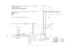
Hi All
Hoping someone can help me help a neighbors son, who decided to swap out their parents old alarm and got stuck.
I’ve managed to do a drawing of what I’ve worked out, but there’s one connection point that we can’t find (guessing under floorboards or carpet). I’ve traced all circuits physically except for the dining room PIR which I did continuity tests and found where some of them come and go to and it’s all marked up on the attached picture.
All the circuits on the left of the drawing are OK, I’ve just not shown the red/black connected to 12v.
The old alarm panel was an Optima XM and had a PIR in the dinning room, that works with just 1 wire to zone 3 and somehow worked via the bell box tamper to 0v – but I’m not familiar with this type of wiring (have only done my own Texecom Premier Elite install).
I know yellow is hard to see, so just to confirm the yellow going to the bell box is connected in the loft to both green and black to the landing PIR.
So, the questions are please:
How might the bell box have been wired? He’s not got a photo prior to disconnection, but says there was more than 1 wire in at least 1 of the terminals. I’m thinking if I can understand the old wiring, I might get the whole system running on the new Texecom Veritas – if it can do the 1 wire to a zone thing?
How might the dining room remaining wires be connected, as the only faults standing are zones 3 and 5?
I’m not at a complete loss as it is, as I know I can just wire the Veritas panel to the external sounder as standard S D C B A, loop out the dining room PIR, and tweak the wiring to the landing PIR so everything else will work, apart from the dining room.
Cheers all


