Piping query

Joined
7 Jul 2010
Messages
42,534
Reaction score
5,857
Location
Retired to:
Country
Portugal
I have asked in the plumbing section (only one reply) but thought I'd try here as well.

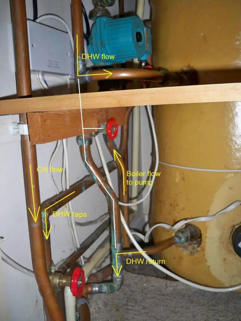
Can anyone see a reason for the 'by-pass pipe' - white line - in this picture?
It's a three-port valve system.

 
Sponsored Links
I have asked in the plumbing section (only one reply) but thought I'd try here as well. ... Can anyone see a reason for the 'by-pass pipe' - white line - in this picture?
It's a three-port valve system.
I presume it's intended as just that (a 'bypass'); Is it closed, or nearly closed? The question obvioulsy is 'why?'.

As you've said in your response in the plumbing forum, at first sight it doesn't really make any sense. All it is 'bypassing' is the DHW heating coil, which is surely already 'very low impedeance' (to keep the discussion forum-relevant :) ) - so one would not have thought that it would serve any safety or pump-preserving function (unless the heating coil got blocked, which is very unlikely). AFAICS, the only effect opening that 'bypass valve' would have would be to reduce flow through the DHW coil (when it was 'operational') and thereby cause it to take longer to heat up the water before the cylinder stat was satisfied.

Having said that, one thought.... Is it possible that, although pretty 'low impedance', the DHW coil is actually appreciably higher impedance than the radiators circuit - so that when the system was doing 'DHW only' the pump (which obviously has to have the same 'setting' all the time), and/or something else, was (or could be) getting unhappy (or having its life reduced) by the pressure generated - and the bypass is there to reduce that pressure during 'DHW only'? During 'CH only', this bypass would presumably be 'out of circuit, and therefore would not reduce flow through radiators. An unfamiliar concept for the Electrics forum, since we are used to having constant-voltage sources (with current varying acxcording to load), rather than constant-current ones (with voltage {aka pressure} varying according to load), but I guess a possibility?!

Kind Regards, John
 
I presume it's intended as just that (a 'bypass'); Is it closed, or nearly closed? The question obvioulsy is 'why?'.
It's closed now. I can't remember how open it was. It cannot be intended to be frequently altered - merely 'set'.
I can't think it anything but a mistake.

As you've said in your response in the plumbing forum, at first sight it doesn't really make any sense. All it is 'bypassing' is the DHW heating coil, which is surely already 'very low impedeance' (to keep the discussion forum-relevant :) ) - so one would not have thought that it would serve any safety or pump-preserving function (unless the heating coil got blocked, which is very unlikely).
It cannot reduce the overall impedance, can it?

AFAICS, the only effect opening that 'bypass valve' would have would be to reduce flow through the DHW coil (when it was 'operational') and thereby cause it to take longer to heat up the water before the cylinder stat was satisfied.
Yes, quite - but no point.

Having said that, one thought.... Is it possible that, although pretty 'low impedance', the DHW coil is actually appreciably higher impedance than the radiators circuit - so that when the system was doing 'DHW only' the pump (which obviously has to have the same 'setting' all the time), and/or something else, was (or could be) getting unhappy (or having its life reduced) by the pressure generated - and the bypass is there to reduce that pressure during 'DHW only'?
But it doesn't, does it? It still has to go through the same pipes before and after.

During 'CH only', this bypass would presumably be 'out of circuit, and therefore would not reduce flow through radiators.
It is and it does not.

An unfamiliar concept for the Electrics forum, since we are used to having constant-voltage sources (with current varying according to load), rather than constant-current ones (with voltage {aka pressure} varying according to load), but I guess a possibility?!
Akin to wiring a switch in parallel with a load - pointless?
 
It looks like a method of flow restriction to the rest of the system, instead of all the water being pumped around the whole system a proportion is returned to the inlet of the pump if the gate valve is opened, the more closed the valve is the more gets pumped around the rest of the system.
It could be that for CH a larger flow is required hence the pump is set to a higher flow rate than needed for just the hot water loop.

Or maybe I have just misread where the pipes go!
 
Sponsored Links
Or maybe I have just misread where the pipes go!
Yes I think you have.

I could understand it may have some purpose if it were between the CH and HW pipes but it is only on the HW pipe from the cylinder inlet to outlet.
 
It's closed now. I can't remember how open it was. It cannot be intended to be frequently altered - merely 'set'.
Sure, but that's the nature of bypass arrangements - 'set' and the time of installation and never altered.
It cannot reduce the overall impedance, can it?
Of course it can - think two resistors (or other loads) in parallel.
Having said that, one thought.... Is it possible that, although pretty 'low impedance', the DHW coil is actually appreciably higher impedance than the radiators circuit - so that when the system was doing 'DHW only' the pump (which obviously has to have the same 'setting' all the time), and/or something else, was (or could be) getting unhappy (or having its life reduced) by the pressure generated - and the bypass is there to reduce that pressure during 'DHW only'?
But it doesn't, does it? It still has to go through the same pipes before and after.
Sure it would. The impedance of the pipes before and after obviously wouldn't change, but the most important part of the impedance of the circuit as a whole is the connection between flow and return (through coil and/or bypass) which would change consdierably if you opened that bypass valve. So, if it was doing 'DHW only', with the pump trying to do its 'constant current/flow' thing, opening that valve would result in an appreciable reduction in pressure at the pump side of the coil/bypass. Again, think of electrical anolgies (given a constant-current source).
Akin to wiring a switch in parallel with a load - pointless?
Well, not just a switch - a switch with a small resistance (aka that valve) in series with it. However, not pointless if one had a constant current source and wanted to reduce the voltage (aka pressure) across the load (hence also across source, aka pump).

Kind Regards, John
 
Maybe it's a deliberate thermosyphon to radiate more heat into the airing cupboard when you want to dry some clothes?

Albeit, a rather short one!
 
EFLI, in terms of the 'just one thought' suggestion I made (goodness knows whether it's the answer!), try a totally electrical analogy ...

Imagine you have a constant-current source (cf CH pump) which gets upset (maybe blows up) if the voltage (cf pressure) across its output rises appreciably above 100V. Imagine that it can be switched to supply one of two loads, one of 90Ω (let's call that 'CH') and the other of 120Ω (let's call that 'DHW'). The actual current supplied by the constant-current source can be 'set', and we have set that at 1A. For the sake of simplicity, ignore the resistance of the wiring.

When switched to CH, all is well, voltage across load (and also across supply, if we're ignoring resistance of wiring) is 90V and everyone's happy. Switch to DHW, then voltage across load (and source) is 120V, and maybe something goes bang.

Now put a 240Ω resistor (let's call it 'Bypass') across the 120Ω DHW load. That's a 'combined' resistance of 80Ω. With the switch in the CH position, it's exactly the same as before - 90V, so all is well (and adding the resistor has obviously changed nothing). With the switch in the DHW position, there is no bang this time, because voltage is only 80V.

As above, I haven't a clue as to whether this was in the mind of the person who installed that plumbing, but if there was a concern that pressures might get too high (and maybe damage pump, or something else) on 'DHW only', there could possibly be some sense in it.

Kind Regards, John
 
It cannot reduce the overall impedance, can it?
Of course it can - think two resistors (or other loads) in parallel.
I admit it can/would in the by-pass pipe and the coil but not at the pump where the same one pipe is connected nor in the same one pipe back to the boiler.

All it can do is reduce the flow through the coil resulting in taking longer to heat the cylinder and returning hotter (less cooled) water to the boiler resulting in hotter water circulating in the hot water pipes.

A thought has just crossed my mind.
Bearing in mind the reply from the plumber regarding the 15mm. out of the coil, do you think that originally (boiler is very old) it did not have a three-port valve - merely a 'T' and so you could adjust the relative flows between the CH and HW?
 
It cannot reduce the overall impedance, can it?
Of course it can - think two resistors (or other loads) in parallel.
I admit it can/would in the by-pass pipe and the coil but not at the pump where the same one pipe is connected nor in the same one pipe back to the boiler.
OK. In contrast with the ('simplified') electrical analogy I posted, you are 'not ignoring the resistance of the wiring'. The analogy (and, indeed, what I was suggesting) relies on the fact that the 'distribution' wires or pipes have fairly 'negligible' impedance in comparison with the 'load' (coil in your case). If it's t'other way around (i.e impedance of coil negligible in comparison with impedance of the rest of the pipework, then, as far as the pump is concerned, reducing the impedance of the (already negligible impedance) coil a bit more with the bypass will clearly make very little difference - which I guess is the way you are thinking.
A thought has just crossed my mind. Bearing in mind the reply from the plumber regarding the 15mm. out of the coil, do you think that originally (boiler is very old) it did not have a three-port valve - merely a 'T' and so you could adjust the relative flows between the CH and HW?
I would imagine that the original setup may well have been as you describe, but I'm not sure how that would/could explain the bypass thingy. My system here is sort-of like having a 3-port valve, in as much as th DHW and several different CH zones each have their own motorised valves. However, despite that, when the plumber put the system together (about 25 years ago) he actually did almost the opposite of your bypass thing, in that he not only deliberately reduced the feed to the DHW coil to 15mm (like 'yours') but also put a gate valve in that 15mm feed and closed it down a fair bit 'by ear/feel'! His excuse/explanation was that "you'll get far too much flow through that there coil if we don't restrict it a bit"!! It made no sense to me - either then or now. It struck me that "too much flow" merely meant that my hot water would heat up quicker! Maybe he thought that it would be noisy? Anyway, I didn't argue, and have lived with it for 25+ years!

Kind Regards, John
 
That's sort of opposite of mine, isn't it.

Does reducing the flow in yours enable the heated water in the coil to transfer more of the heat to the cylinder rather than rushing through?

Whereas in mine it just lets more of the heated water bypass the cylinder altogether which seems pointless.
 
Does reducing the flow in yours enable the heated water in the coil to transfer more of the heat to the cylinder rather than rushing through?
Slowing the flow through the coil down not only reduces the entry/exit delta temperature, but also increases the reheat time of the cylinder, as the end of the coil will be a lot cooler than it needs to be.

Reducing the return temperature allows the boiler to run more efficiently, but slowing the flow rate to achieve this can only be done by pump settings (and that's usually linked to the size of your CH installation). Adding a bypass to the cylinder just reduces all the system efficiencies.
 
That's sort of opposite of mine, isn't it.
Indeed so - I wrote:
...he actually did almost the opposite of your bypass thing...
Does reducing the flow in yours enable the heated water in the coil to transfer more of the heat to the cylinder rather than rushing through?
I've often thought about that, but my head goes around in circles a bit! With a slower flow, there will be greater extraction of heat per volume of 'coil water' (hence temperature of 'coil water' will drop more during its passage through the coil), but there will be less volume/time of coil water delivered. With higher flow, there will be less extraction per volume of 'coil water' (hence temperature of water will drop less during its passage through coil), but there is a greater volume/time of coil water being delivered. Which of those opposing effects 'wins', I haven't a clue! They might end up much the same!
Whereas in mine it just lets more of the heated water bypass the cylinder altogether which seems pointless.
Indeed. As I said, my immediate reaction, like yours, was that it didn't make sense, for that reason. My 'just another thought' proposal was a desparate attempt to see if I could think of any way in which is could be rationised/justified, but I suspect that's not the reason. As you say, I suspect that it's just a 'mistake'.

Kind Regards, John
 
Reducing the return temperature allows the boiler to run more efficiently, but slowing the flow rate to achieve this can only be done by pump settings ...
Only? What if, like my system, that flow reduction is achieved by a restriction in the feed to the coil?
Adding a bypass to the cylinder just reduces all the system efficiencies.
That's certainly what common sense says, and was the initial reaction of both EFLI and myself. If you haven't already seen it, you may be amused to see the response that EFLI got in the plumbing forum. I wonder if, like electricians, plumbers are meant to understand what they're doing and saying? :)

Kind REgards, John
 
..he actually did almost the opposite of your bypass thing...
Oh sorry, must have skipped that bit. I wondered where I got the idea. :)

I've often thought about that, but my head goes around in circles a bit! With a slower flow, there will be greater extraction of heat per volume of 'coil water' (hence temperature of 'coil water' will drop more during its passage through the coil), but there will be less volume/time of coil water delivered. With higher flow, there will be less extraction per volume of 'coil water' (hence temperature of water will drop less during its passage through coil), but there is a greater volume/time of coil water being delivered. Which of those opposing effects 'wins', I haven't a clue! They might end up much the same!
Yes, the only advantage I can think of is less heat loss on the return to the boiler.

As you say, I suspect that it's just a 'mistake'.
Yes, thank you for the input.
 

DIYnot Local

Staff member

If you need to find a tradesperson to get your job done, please try our local search below, or if you are doing it yourself you can find suppliers local to you.

Select the supplier or trade you require, enter your location to begin your search.


Are you a trade or supplier? You can create your listing free at DIYnot Local

 
Sponsored Links
Back
Top