Question about Loft socket

B

busterboy

Hi

Im new to forum and just want to ask a question.

(Refer to diagram 1 for this part)

I live in an old stone cottage that over the years has had kitchen extension on back and one bedroom added at front upstairs.
This will be a bit hard to explain but please bare with me.
Because of the age of the house a new kitchen has been added to the back and built on to the stonework and the same for the upstairs bedroom (Bedroom 3)

I have made a diagram to try to explain this better. But above bedroom 1 have floored the loft and this is where i want to add a double socket.

in the other half of the house is loft 2 but these lofts are separated by the new bedroom upstairs (bedroom 3). all wiring that goes from one side of the house goes through bedroom 3's floor boards.
Again I'm sorry for the confusion but just trying to explain the setup before i ask about my question.

(Refer to diagram 2 for this part)

Now in bedroom 1 there is only one double socket and it looks to be a spur as it only has one cable going to it. so i don't think i can use this to spur of for another socket in the loft 1 which is directly above it???

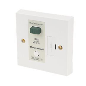
but in loft 2 there is a spur running out to the outbuilding with 3 sockets linked to it. where it leaves loft 2 there is an what looks to be a mini trip or switch with ON/off on it. (I can provide pictures if this helps.) when its one the outbuilding sockets work and when you flip it to off they don't so that's fine.

(diagram 3)
Now for my question if you are still with me lol! I am thinking about disconnection the wire that runs from loft 2 to the out building and adding a new wire to the on/off trip switch that will follow back through the floor boards of bedroom3 and into loft 1 so i can add a double socket to it. i have outlined this is a basic diagram to try to explain it better. i would be great full if someone can point me in the right direction on this and advise me if this would work. I don't need sockets in the outbuilding and have ducting already in place for the stone walls so the new cable will install easy. I also think the on/off switch could be a fcu as the outbuilding sockets seem to be spurred from the house but not sure about this hence any advice welcome. i can provide photo of this switch if necessary.

Thank you.


P.S

Not sure how to upload my digrams but i think there in an albums section if thats any use.
 
Sponsored Links
EFLImpudence
thankyou for pasting my diagrams under the topic.
 
Sponsored Links
Would it be better or easier to run from the socket in Bed 1 if it were possible?
What is the rating of the fuse or circuit breaker in the consumer unit which isolates this socket?

If not, how (by what route) does the cable get from the switch to the loft?


A picture of the switch would probably help.

Bedtime now, someone else will be along.
 
Now in bedroom 1 there is only one double socket and it looks to be a spur as it only has one cable going to it. so i don't think i can use this to spur of for another socket in the loft 1 which is directly above it???
By swapping the existing socket for a fused connection unit you could then likely add any amount of sockets from that and still be within regulations. But first question has to be size of fuse/MCB feeding that socket.
but in loft 2 there is a spur running out to the outbuilding with 3 sockets linked to it. where it leaves loft 2 there is an what looks to be a mini trip or switch with ON/off on it. (I can provide pictures if this helps.) when its one the outbuilding sockets work and when you flip it to off they don't so that's fine.
That sounds like a RCD FCU it would do two things one it has a fuse and two it senses an earth fault.
(diagram 3)
Now for my question if you are still with me lol! I am thinking about disconnection the wire that runs from loft 2 to the out building and adding a new wire to the on/off trip switch that will follow back through the floor boards of bedroom3 and into loft 1 so i can add a double socket to it. i have outlined this is a basic diagram to try to explain it better. i would be great full if someone can point me in the right direction on this and advise me if this would work. I don't need sockets in the outbuilding and have ducting already in place for the stone walls so the new cable will install easy. I also think the on/off switch could be a fcu as the outbuilding sockets seem to be spurred from the house but not sure about this hence any advice welcome. i can provide photo of this switch if necessary.

Since you would seem to have a RCD FCU
ae235
these units are not normally used when you have a RCD in the main box so I would think the main box does not have one. This means to add buried cable or extra sockets the easiest way to comply with the regulations is to use more RCD FCU to extend with. At £17 each not really expensive and it means swapping a socket for one of these you can then replace that socket next to the RCD FCU and also daisy chain from it.

There was a change in 2008 when it was decided that all new sockets should be RCD protected which in turn means unless there are RCD's fitted in the consumer unit it becomes hard to extend an existing ring within the rules with out using a RCD FCU and spurs method.
 
You have a few options but first you need to investigate the circuit of the socket in bedroom one, it maybe a radial circuit that can be spurred from, it maybe that you can locate a fused connection unit (FCU) prior to this socket if already a spur from ring final, then add any number of sockets after that. But it could also be that it is already a spur from a spur, so investigation required.
Looking at the fuse rating, cable size and number of cables connected to the fuse/breaker will be a good starting point, but this would not absolutely prove the type of circuit it is, as it possible to have two cable at fuse/mcb and still be a radial circuit, also it is possible to be ring final, if only one cable is at fuse/mcb, I have seen many times where both legs of ring were in separate fuse/breaker.
So only by testing could you prove the circuit type.
Or
Using the FCU powering the outbuilding you could take a feed from that point, even extending the circuit or fitting a second FCU, could be done without power-loss to outbuilding. `

Regulations require new sockets to have 30mA RCD protection, also cable must be routed within the permitted safe zones.
Wiki will offer information to help.
 
i have included a picture of the on/off switch and followed where cables go to and from. I have also documented the consumer unit to show what does what. please use my diagrams that are number to refer to bedroom 2, loft 2 ect i hope these all help to explain things a bit better.

the on/off switch has a front cover and when removed i found a fuse inside. (see pictures). it looks like an old set up and i would renew this if i can run my cable from here to loft 1 for a double socket in loft 1. again i do not need any power to the out buildings so that is why i though of running a new cable from loft 1 to the on/off switch in loft 2 and just disconnecting the wire that runs out to the out buildings and connect in the new wire from loft 1.

The junction box loft 2

the junction box has 5 wires coming from it.
1 goes to the emergency heater.
1 goes to the bedroom 2 socket.
1 goes to the on/off switch which then heads on to the out building
2 go back through the wall ( I think one of these has to be a supply though but not sure)


i have included the pictures from the consumer unit and electricity meter so that you can see yourself what the ratings for total load say. i cannot find any fused in this just switches that look like mini trips that blow when a fault or overload occurs but you can see for yourself what i mean from pictures.


anything else i can provide to help just ask and i will do my best. again I'm not sure how to put pictures under my text here but they will be in albums if that helps.


Thanks again.

View media item 65917 View media item 65918 View media item 65919 View media item 65920 View media item 65921 View media item 65922 View media item 65923 View media item 65924 View media item 65925 View media item 65928
 
i have added the junction box layout to diagram 1 to make it more easy to understand. I have also added the new idea for the double socket in loft 1 using the green line.

Hope this helps.
Thanks

**image is in albums[/img]
 
Well, it all looks rather old.

As the circuit is on a 20A mcb, although it is impossible to tell for sure, it would appear to be a radial circuit, in which case you could do as you wish.

However, new sockets and wiring concealed in walls without earthed mechanical protection must be protected by a 30mA Residual Current Device.

You would be advised to fit an RCD FCU at the origin of your new wiring.
The fuse switch could also be replaced with an RCD FCU to protect the outside circuit(s).
It could all do with tidying and terminating correctly.

Also the routing of the new cable must be in the safe zones -
//www.diynot.com/wiki/electrics:installation_techniques:route
//www.diynot.com/wiki/electrics:installation_techniques:walls

I would advise that you have the installation inspected as, looking at it, anything could have been done.
 
thanks for reply.

if its a radial circuit could i take a spur from socket in bedroom 1 in loft 1 and use that??

it would be a lot easier if i could use the socket in bedroom 1 to spur of but as i said there is only 1 cable going to it so can i

option A
splice into bedroom 1 socket cable in the loft 1 using a junction box to add a new socket in loft 1

or

Option B

Splice into bedroom 1 socket cable in loft 1 using junction box and add a fcu then a new socket.
 
if its a radial circuit could i take a spur from socket in bedroom 1 in loft 1 and use that??
Yes, if it is on the 20A mcb but you must still have RCD protection.

it would be a lot easier if i could use the socket in bedroom 1 to spur of but as i said there is only 1 cable going to it so can i
Apparently.

option A
splice into bedroom 1 socket cable in the loft 1 using a junction box to add a new socket in loft 1
You will have to do B


or

Option B

Splice into bedroom 1 socket cable in loft 1 using junction box and add a fcu then a new socket.
Yes, you can use the RCD FCU as a junction box.

You could position it at the origin of the cable or anywhere convenient as it will have to be readily accessible.
 
Looks like to me you need a new fuse box and a re-wire to bring up to current regulations. :eek:

Andy
 
The isolator that switches everything off, could post some detail and a better close up picture of this?
Does everything includes the outhouse?

There are few non-conformities on you installation, that ideally would need addressing.
 

DIYnot Local

Staff member

If you need to find a tradesperson to get your job done, please try our local search below, or if you are doing it yourself you can find suppliers local to you.

Select the supplier or trade you require, enter your location to begin your search.


Are you a trade or supplier? You can create your listing free at DIYnot Local

 
Sponsored Links
Back
Top