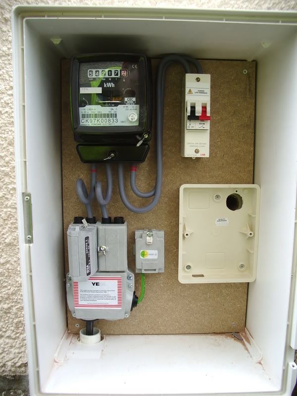
Hello chaps, the other day, I posted the following onto IET Forums and lets be honest, the effort went to waste as only some were actually interested in helping, others were too fussed about who is going to do the work, how they will do it, the qualifications they will have to hold, why I am butting in...and all sorts. I then pointed out that I never did want to carry out the works myself, and instead want to apply whatever is gained from the responses to my studies. Its like the thought of me telling them I am pursuing a career in electrics, offends them!! Terrible I must say.
Anyhow, I mentioned that I would be posting onto this forum as the peepz on here are far more understanding than their lot!! Never again will I use that forum I tell u, (this is my personal opinion, some may disagree)
All I am after is a step by step guide to changing an ordinary domestic fuse box to a CU. I am not that competent to carry out the work myself as am aware there are several tests etc involved, before and after installation, I will be using the knowledge acquired to aid with me with studies, plus showing off to the spark I call in once I know the nature of the works involved!!
It is a 3 bedroom house for which I am the landlord. A tenant asked me whether the electrics in the house were up to scratch, I wasn't too sure until I checked the fuse box and surrounding area. I opened up all socket outlets and found no issues whatsoever, all wire sizes seem to be correct throughout the house. No fancy showers, no electric cookers, no outdoor lighting, no additional spurs even. Just a heavy load on the downstairs ring, i.e. washing machine, dishwasher, microwave, kettle etc. (Like an individual once said, a typical grannys house JohnD is the culprit) The 2 issues I came across were no equipotential bonding at all throughout the house, and the grannified fuse box!
I have posted these pics previously:
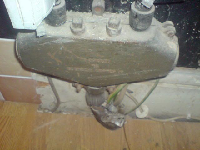
Protection with a 100A fuse:
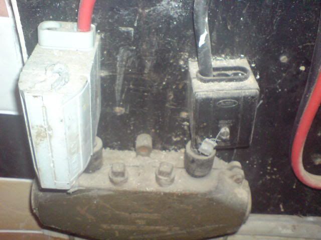
Into the meter:
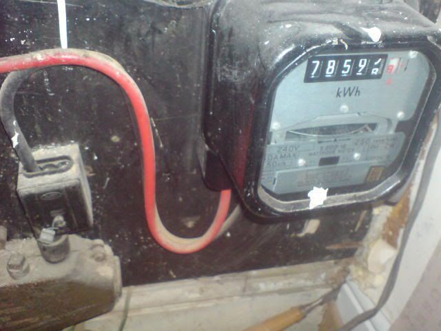
and into the fusebox:
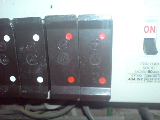
How would a qualified spark go about rectifying the above. I know RF mentioned a replacement CU last time with 2 x 32A RCBO's, but would this be a straight swap. If the original fusebox had a max total demand value of 60A, could this be replaced with a 100A CU without having to upsize the cables going from the meter into the fusebox???
(original post : //www.diynot.com/forums/viewtopic.php?t=87043&postdays=0&postorder=asc&start=0)
And what sort of tests do you guys perform prior to and after works? Ze, Zs?? Do you have special equipment to obtain these results?
Anyhow, I mentioned that I would be posting onto this forum as the peepz on here are far more understanding than their lot!! Never again will I use that forum I tell u, (this is my personal opinion, some may disagree)
All I am after is a step by step guide to changing an ordinary domestic fuse box to a CU. I am not that competent to carry out the work myself as am aware there are several tests etc involved, before and after installation, I will be using the knowledge acquired to aid with me with studies, plus showing off to the spark I call in once I know the nature of the works involved!!
It is a 3 bedroom house for which I am the landlord. A tenant asked me whether the electrics in the house were up to scratch, I wasn't too sure until I checked the fuse box and surrounding area. I opened up all socket outlets and found no issues whatsoever, all wire sizes seem to be correct throughout the house. No fancy showers, no electric cookers, no outdoor lighting, no additional spurs even. Just a heavy load on the downstairs ring, i.e. washing machine, dishwasher, microwave, kettle etc. (Like an individual once said, a typical grannys house
I have posted these pics previously:

Protection with a 100A fuse:

Into the meter:

and into the fusebox:

How would a qualified spark go about rectifying the above. I know RF mentioned a replacement CU last time with 2 x 32A RCBO's, but would this be a straight swap. If the original fusebox had a max total demand value of 60A, could this be replaced with a 100A CU without having to upsize the cables going from the meter into the fusebox???
(original post : //www.diynot.com/forums/viewtopic.php?t=87043&postdays=0&postorder=asc&start=0)
And what sort of tests do you guys perform prior to and after works? Ze, Zs?? Do you have special equipment to obtain these results?


