- Joined
- 5 Sep 2024
- Messages
- 6
- Reaction score
- 1
- Country

Hello
Yes it’s another post about TPone and Hive!
Our old house had a single zone and hot water. And due to a special offer, we had Hive installed. Overall we thought Hive was good, especially the boost buttons and voice control.
Having moved, we now have a condensing boiler with two heating zones and hot water. Hive were having a summer sale (pure coincidence) but this time they could not offer any installation. So I channelled my inner Clarkson and thought “how hard can it be?”
First thing I noticed was that there is nothing in the boiler cupboard, except the boiler – no controller. The lump on the wall contains the thermostat and the timer/controller. The downstairs unit also controls the hot water.
At this point I came across the name John Ward in a post on this forum. After watching a couple of his videos on YouTube, I thought that it should be possible to put the receivers in the airing cupboard.
The hot water tank has three plastic ‘boxes’ on the outside. In our case the wiring is in the middle one. The lower one has the cylinder thermostats and immersion heater. The upper one has a second immersion heater & thermostat, but it’s not wired.
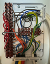
The first photo below shows the current wiring inside the box. The cables on the bottom go to the three valves, the hot water thermostat and the pump. On the right side, the top one seems to be Line, Neutral, Earth and ‘boiler on request’. The lower one seems to be Earth and the three calls for heat from the wall thermostats.
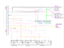
The second snip is a schematic showing my understanding of the system as it currently is. Because brown and black look very similar, I have replaced brown with pink. White has also been replaced by yellow. The valves are drawn in full as they were (for me) the most difficult bit to get my head around. Most earth and neutral wires are indicated, but not drawn – the drawing is complex enough. It’s a similar story with the pump – it only has LNE and the line comes from terminal 3. All the pre-installed links are shown on the left side of the terminals.
My plan to install Hive.
1 remove the Brown, Black, Grey wires from terminals 14, 13, 7 (call for heat from the existing thermostats).
2 wire Line and Neutral to the two receivers – probably from terminal 16 (vertical) and terminal 3 (horizontal).
3 add wire from terminal 14 to terminal 4 on the 2 channel receiver – CH zone 1.
4 add wire from terminal 7 to terminal 3 on the 2 channel receiver – DHW.
5 add wire from terminal 13 to terminal 4 on the single channel receiver – CH zone 2.
6 That’s it, apart from getting the hub on line, pairing the receivers, sorting the time/temp schedules…
Anyone spot my ‘deliberate’ mistakes?


