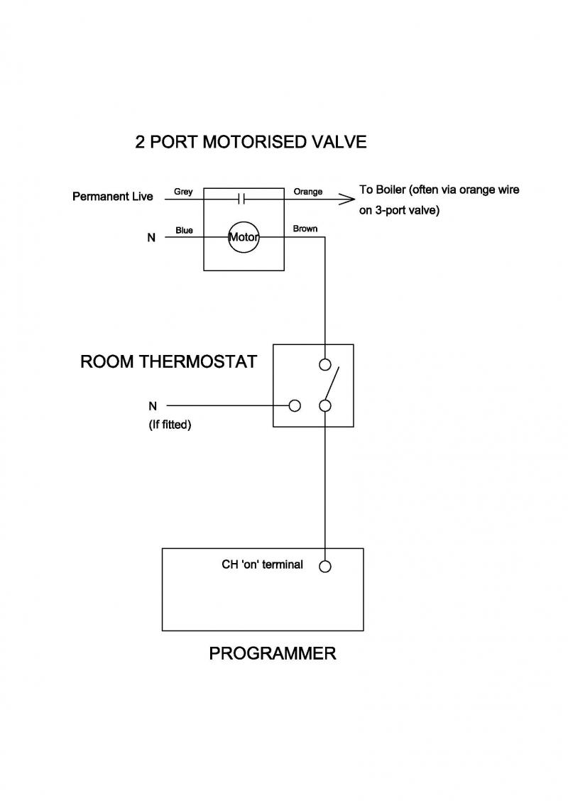
I've seen a couple of these, one was a house with a granny annexe and the other was a house with a separate office. In both cases they were wired exactly as a traditional 'Y' plan, with the 2 port motorised valve added on as per my sketch below. You probably won't find an official diagram, because it's a flawed system and unlikely to be recommended.
Depending on the installers preference, the grey and orange wires from the mircroswitch on the 2 port valve may be transposed. I would use the orange wire for the switched live so that it followed the same convention as the 3 port valve.
However, as I said earlier, there is a fundamental flaw with a combined Y and S plan. Assuming both valves receive their flow directly from the boiler, when the heating circuit fed from the 2 port valve is calling for heat and the system is running, the three port valve does not physically have the facility to close off both of its outlets simultaneously, so whatever port is open also receives a flow from the boiler whether it's required or not. This could be cured by replacing the 3 port valve with two, 2 port valves which would allow both to be closed simultaneously, and making it a full S plan. [If this was done, a by-pass loop would also need to be added for a pump run on.]
In an alternative type of installation in a village hall, the 2 port valve supplying the main room teed off the heating flow after the 3 port valve. In this scenario the purpose was only to turn off the main room heating when it got too warm because of high occupancy, so the microswitch in the 2 port valve was not connected. Meanwhile, the entrance and toilets were kept on by the 3 port valve. In this instance it would not be possible to have the main room heated, without the auxiliary rooms also being on and calling for heat.
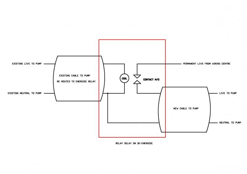
However in your case, if the existing system is working satisfactorily for the clients, you don't need to change the functionality to add a run on facility. If the boiler doesn't have the facility built in, a 'delay on de-energise' relay can be wired into the existing pump wiring as follows. (Sorry it's a bit hard to read, it's a sketch I made some time ago when I was learning how to draw)
Hope this helps. I would be interested to hear how you get on.


