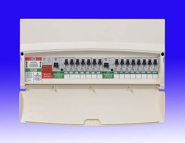
First bit of advice would be to swot up on the terminology

Not trying to be rude but it is very difficult to give answers when your question makes no sense.
An FCU will never contain an MCB, but a CU (consumer unit) will. When you say 'main electricity board power switch' do you mean a dedicated isolator installed before you consumer unit by the electricity board or are you calling the consumer unit the 'electricity board'.
I'll answer your questions based on a few assumptions:
When you say FCU you really mean CU:
When you say 'main electricity board power switch' you really mean a main isolator placed BEFORE your CU but AFTER the electricity meter.
I'm also going to assume that you know how to safely confirm the supply is isolated and that you know how to, and will, upon completion, test the circuit to ensure compliance with BS7671... *cough*
1) Switch off the main isolator and confirm that the system is dead (please do NOT use a neon screwdriver for this).
2) Remove the front cover of the CU. At the very bottom there may well be a plastic shield that you need to remove, this shield covers the copper busbar which is connected to the bottom of each MCB.
3) Loosen the top and bottom terminals on the MCB that you want to replace and probably the lower screws of all the modules that are connected to the same busbar. When you do so the copper busbar should drop out to reveal a little tab at the bottom rear of the MCB which you need to pull down with a screwdriver to unlock the MCB from the din-rail.
4) Clip the new MCB in place, reinstall the busbar (making sure all connections are tight) and then reconnect the supply cable into the top of the MCB (ensuring it is within the tunnel terminal and not just wedged behind it.
5) While you have the cover off tighten up the rest of the terminals and then refit the busbar cover followed by the CU cover.
6) Switch the electricity back on and assuming you haven't disturbed anything while you were working, make yourself a cup of tea.


