Tests cirucits help

Joined
14 Oct 2023
Messages
149
Reaction score
3
Country
United Kingdom
Hello good people

I haven't worked in the industry and I have DIY experience.

I am studying the course at York college.

I have a practical exam coming up. So i just want to get some practice in beforehand. Got a couple of months left yet.

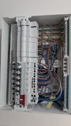
I've made or should I say attempted to make a little sketch of the board will be.

The consumer unit will have RCD protection although this board doesn't seem to have it.

Can someone please kindly walk through how to do some of the tests. Especially on rlthe ring circuit.

Ofcourse once the safe isolation is done... I've turned off everything. Etc etc.

I'll perform the dead tests and then move onto live tests.

My idea is start off with continuity . Link
Cpc to live at breaker. Check all lightings etc sperarely switch lamp. Then move onto the heater .

Repeat with line and neutral.. how would i do the ring and bonding and the metal tray? ? Would it be long lead method?

Then once that's done. Move onto Insularion resistance at 500v. 3 tests on each circuit.

Then live and rcd. I've not really done this before. I'll need to read more on this one.

Any help would greatly be appreciated.

Thank you Snapchat-7344927.jpg
 
Follow the CRIPPLER method.

C ontinuity of cpc and bonding conductors. R2 wander lead.
R ing continuity.
I .R test
P olarity DEAD test
P olarity LIVE test
L oop impedance test, Ze and Zs
E arth fault and PSC fault current
R cd and other functional tests. (Ramp tests etc).

The practical at college should guide you first and you'll normally get a demonstration then they will ask you to do it just before the exam.
 
To test a ring circuit disconnect the 6 conductors from the board,

test continuity ,
live to live,
neutral to neutral
earth to earth

record the results in ohms, the live and neutral result will be similar and the earth result will be roughly 1.67 x the line and neutral result (assuming 2.5mm L and N and 1.5mm earth)

Then connect live 1 to earth 2 and live 2 to earth 1 creating a figure of 8

Then go round to each socket and test between live and earth, this result will be recorded as your r1+r2.... also this result should be a quarter of the live loop and the earth loop you did at the start added together and divided by 4.

When testing at each socket the result should be roughly the same which should mean the sockets are part of the ring.


I'll await my bashing...good luck with your course mate.
 
But the reality of testing old installations the figure of 8 test will more often than not give a variety of results, plus there will almost certainly be spurs too

Trainers and courses make out that figures are consistent but in truth unless the installation is brand new , with no spurs

Get as much testing experience as you can, as you’ll need it most when doing fault finding

Do you have proper test kit?
Very true but for the sake of passing the course it's what he will need to do.
 
2
To test a ring circuit disconnect the 6 conductors from the board,

test continuity ,
live to live,
neutral to neutral
earth to earth

record the results in ohms, the live and neutral result will be similar and the earth result will be roughly 1.67 x the line and neutral result (assuming 2.5mm L and N and 1.5mm earth)

Then connect live 1 to earth 2 and live 2 to earth 1 creating a figure of 8

Then go round to each socket and test between live and earth, this result will be recorded as your r1+r2.... also this result should be a quarter of the live loop and the earth loop you did at the start added together and divided by 4.

When testing at each socket the result should be roughly the same which should mean the sockets are part of the ring.


I'll await my bashing...good luck with your course mate.


This is great info mate. Honestly appreciate it. I'll have a little crack at this aat home in abit and see how I get on and ill update :)
 
But understanding why figures vary and having this knowledge is immensely useful

Lack of continuity of conductors on rings is incredibly common

Understanding is the key thing.
 
To test a ring circuit disconnect the 6 conductors from the board,

test continuity ,
live to live,
neutral to neutral
earth to earth

record the results in ohms, the live and neutral result will be similar and the earth result will be roughly 1.67 x the line and neutral result (assuming 2.5mm L and N and 1.5mm earth)

Then connect live 1 to earth 2 and live 2 to earth 1 creating a figure of 8

Then go round to each socket and test between live and earth, this result will be recorded as your r1+r2.... also this result should be a quarter of the live loop and the earth loop you did at the start added together and divided by 4.

When testing at each socket the result should be roughly the same which should mean the sockets are part of the ring.


I'll await my bashing...good luck with your course mate.
I live in a flat. It says its protected by and RCD.. but I can't see the button . I'm assuming it'll be in the main consumer unit for the block ?

Judging by just looking at CU opened . It seems the kitchen sockets and the general sockets have 2 seperate rings as they have 2 sets of lines and neutrals coming into the MCB. And correct me if I'm wrong the larger neutral wires coming into the back of the MCB from the RCD ???

I might do some continuity tests.
 

Attachments

  • Snapchat-783723378.jpg
    Snapchat-783723378.jpg
    237.3 KB · Views: 25
  • Snapchat-1864186669.jpg
    Snapchat-1864186669.jpg
    223.6 KB · Views: 24
Be a bit careful mate, if I was you I'd probably mock up 4 or 5 sockets on a board just to get the hang of it.

The rcd test button is marked T

Screenshot_20250306-162518_Chrome.jpg
 

DIYnot Local

Staff member

If you need to find a tradesperson to get your job done, please try our local search below, or if you are doing it yourself you can find suppliers local to you.

Select the supplier or trade you require, enter your location to begin your search.


Are you a trade or supplier? You can create your listing free at DIYnot Local

 
Back
Top