The most basic problem with DIY work

Joined
20 Aug 2009
Messages
10,288
Reaction score
1,472
Location
Dorset
Country
United Kingdom
While some of the general problems with DIY work include not stripping cables to a workable length, using earth sleeving, grommets, etc...

...the most common problem is tightening the wires to the terminals.

People just can't do it.

All too often, some handyman will replace a socket. You feel compelled to check it if it's an installation you've been heavily involved with, and the wires just fall out, or you can easily tighten up the screws more.

The other problem is wires snapping at the terminal, where an end needed restripping. Or sometimes an end needed doubling over to give it more strength.

Related to this is trapping the insulation under the screw.

All the time householders/builders/plumbers claim they have connected something 'for you', but you have to check it if it's part of your work.

There's not a lot on this forum (as far as I know) on basic techniques as connecting a wire to a terminal. It's seemingly so basic, yet people can't do it.

Is it that they're not strong enough, or don't want to damage the wire? Or just not thinking?
 
Sponsored Links
Part and parcel of the problem might be the crap hard single core copper that is now used for domestic wiring. Oh for the good old days of tinned reasonably-soft multi-stranded copper.
 
The problems with slack cables in terminals is not restricted to DIY. Working on a batching plant we had a service schedule which included checking terminal tightness. And yes vibration did cause wires to become slack and continual tightening would cause the wires to be severed. Over the years there have been many attempts to stop this problem including torque screwdrivers but it would seem the maintenance free terminal has been a real break through.

I did not like these when I first saw them be it the full blown terminal or the spring coils to connect the earth on a cable joint kit. I personally could not see how any terminal could vibrate lose when encapsulated in epoxy resin?

With 1 mm² control cables I must admit the spring loaded maintenance free terminal works well but as the size goes up the chance of necking of a cable through maintenance tightness checking is reduced and the spring pressure required for good contact increases so I still don't like them with 32A circuits.

I was brought up with the idea one wire to a hole and building panels would install terminals and links so there was no need to put two wires in the same hole. Yet that is what we do with sockets on a final ring. In fact up to three wires per hole.

So does the team think sockets should have multi-terminals?

I will always tighten then stack off to insert wires terminals carrying heavy loads as I have come across bad threads where the thread binds rather than tightening on the wire. (also with stranded a strand in thread). Problem is when they heat up and cool down it releases the binding of the thread so on inspection later people will always blame the installer for not tightening correctly.

However in the main I was maintenance and time was not as cut and dried as with installation. For installation guys to test every screw would just be too time consuming.

So lets have some ideas. How would you ensure the correct torque is used on terminals? I have tried torque screwdrivers and unless you were to give the torque settings with the sockets they will not work. One does get a feel and sense when something is wrong with a terminals thread but how one would describe that
 
Sponsored Links
I like your one-hole-per-wire concept for domestic sockets but this would raise the cost and people simply don't want to pay. We all moan about cheap crap but are reluctant to pay for decent stuff. Do any companies currently sell such domestic sockets.
Many years ago I saw an American installation system whereby wires were all terminated within the mounting box. So, once the wires were terminated they were not disturbed by fitting the faceplate. Then the faceplate/socket was simply plugged into the box. This alleviated the possibility of wires working loose as the typical British faceplate was pushed onto the box, bending the connecting wires so's the faceplate screws could be tightened.
I like the termination design whereby the fixing screw jacks a clamping bar against the wire rather than acting directly onto the wire itself. However even these fail to guarantee good wire trapping where wires of differing size are clamped into the same termination or wires are bunched so that they are not evenly clamped, so back to the 1 wire per hole system.
As regards spring loaded systems, I have concerns about terminal heating causing the spring to lose temper and hence tending to slacken the clamping pressure which in turn increases the thermal effect etc. Maybe this concern is unfounded.
 
I have concerns about terminal heating causing the spring to lose temper
Where the spring is not in direct contact with the wire and is not part of the circuit the heating in the spring should be negligable so the contact should remain servicable after transient high currents.

Where the spring blade is also the main contact with the wire there is a high risk of the spring softening as a result of heating from the contact area.
 
CEF's sockets (RPP brand) have two terminals per connection point.
 
I was brought up with the idea one wire to a hole and building panels would install terminals and links so there was no need to put two wires in the same hole. Yet that is what we do with sockets on a final ring. In fact up to three wires per hole. So does the team think sockets should have multi-terminals?
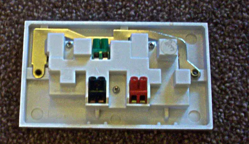
I certainly think it would be a very good idea - and not only sockets. We already have ceiling roses which, at least for straighforward circuits, only require one conductor per hole, and a few (but not all that many) JBs (including 'MF' ones) which do. As I have asked a number of times here (but have never got a response), does anyone still make sockets like this? (of which I have a few used specimens in my cellar):
So lets have some ideas. How would you ensure the correct torque is used on terminals? I have tried torque screwdrivers and unless you were to give the torque settings with the sockets they will not work.
If there were 'recommended torque settings' specified, I wonder if they would actually be satisfactory ones? As I've observed before, in case of MCBs, RCDs, 'Main Switches' etc., if I tighten the terminals to the manufacturer's recommended torque, I can then usually get (immediately) at least quarter of a turn more by hand, without excessive effort - which rathers me.

Kind Regards, John
 
I have concerns about terminal heating causing the spring to lose temper
Where the spring is not in direct contact with the wire and is not part of the circuit the heating in the spring should be negligable so the contact should remain servicable after transient high currents. Where the spring blade is also the main contact with the wire there is a high risk of the spring softening as a result of heating from the contact area.
It's often hard to know whether the spring counts as a 'main' contact (they are often such that they will carry some current, but also push the conductor against other metallic parts of the terminal), but I don't think I've seen one in which the spring is not in (electrical annd thermal) contact with the conductor.

Kind Regards, John
 
I remember with jump leads I always put earth braid between the two sides as if there was a bad connection on the side with cable attached it would burn hinge and temper spring.

The central heating controls often have the plate with contacts idea but to do that the plate would need to be surface. And if we think back to the old 15A sockets they also had a cover which was removed and the socket wired and cover replaced. The same is true for many extension lead sockets.

With solid or large strand cable the screw direct onto cable is not really a problem but with multi-strands either pin-crimps or the fixing screw jacks a clamping bar is required. So for example in a caravan the clamp rather than direct screw is required. But buying from likes of screwfix one does not see what one is buying and terminal type is not in the description. At £7.50 for 5 they are cheap so I would not think so.
 
As to torque setting I remember with cars having a torque setting for cylinder head bolts however the idea was flawed and a series of ideas were tried to ensure correct torque or more to point holding down pressure. Rover with V8 tried a special lubricant on bolts but latter the idea seemed to be a start torque to ensure contact and then an extra set amount of degrees turn. Also renewing bolts every time the head was removed.

This is clearly not an option with 13A sockets and the problem would be different size screws and different thread pitch would require a different torque setting. The screwdriver would have to be supplied as part of the socket kit.

The idea of shear bolts would also work but you would be unable to re-use any sockets.

The socket shown by JohnW2 would likely help but not sure if they would comply with the BS requirements as we can have 4mm² or even 6mm² cable feeding a modern socket and I question if it would fit in those terminals and clearly you could not have a spur.

What we would need is something similar to a grid switch where there is a final plate fitted and the terminals can be accessed for inspection and testing without disturbing the socket. But as rightly said cost rules it out.
 
Many years ago I saw an American installation system whereby wires were all terminated within the mounting box. So, once the wires were terminated they were not disturbed by fitting the faceplate. Then the faceplate/socket was simply plugged into the box.
That's a BGI.

It would need BS 1363 to be amended, or a new EN to be introduced. It might be simpler to introduce, and of wider interest if the back-boxes could accommodate BS 1363, BS 546 (why not?), and all the various CEE 7/x accessories. At the back or sides there could also be provision for plug-in connections to the fixed wiring, making it of interest to the prefabricated wiring market. The size would start to grow (maybe no single-gang versions?), but I can envisage a way to unplug a socket and plug in an FCU, which would connect to a set of outgoing terminals not active when a socket was in place.

Decorating would become easier - just pull the accessories off, no need to turn off the circuit, no need to break the circuit. Ditto changing accessories. For decorating a cheap plastic cover could be made to allow painting.

Test equipment manufacturers could make just one type of adapter to go into the back box instead of several for all the socket types.


As regards spring loaded systems, I have concerns about terminal heating causing the spring to lose temper and hence tending to slacken the clamping pressure which in turn increases the thermal effect etc. Maybe this concern is unfounded.
As long as the circuit is properly designed and installed, there is no way that the spring would get anywhere near hot enough to affect its temper.

[EDIT]Silly typo corrected[/EDIT]
 
The socket shown by JohnW2 would likely help but not sure if they would comply with the BS requirements as we can have 4mm² or even 6mm² cable feeding a modern socket and I question if it would fit in those terminals and clearly you could not have a spur.
The one I pictured is a very old one (removed from service a good few years ago), and I don't know what Standards it complies with nor what the terminal capacity would be - but it was the concept I was talking about. As I've suggested in the past, the ideal (which I imagine would/could probably be BS1363-compliant, although I'm not certain) would be to have three 'holes' for each of L, N & E, each large enough to take at least 4mm² conductors - hence enough for 'spurs' and for branches in radials. I doubt that the manufacturing costs (after design and tooling up) would be appreciably higher than what we now have - just a little more brass and half a dozen extra holes and screws.

Kind Regards, John
 
IF it weren't for the fact that I know that the clueless would screw up, I'd suggest removable jumpers between the L & N pairs to allow a ring final to be broken into and extended.
 
Ah the "loose screw" concern.
I really do wonder as a percentage of the total number of installed pieces of screw terminal equipment how many come loose in a year?

I would suggest it would be very, very small and the problem is quite possibly overstated.

We have about 5,000,000 cut-outs we don't have a particular problem with the "vibrating" loose, we don't go round checking for tightness on a regular basis so I do really wonder if this is the problem it is.
The only ones we see as a risk are those with a solid aluminium core where we must use a torque limiting device.

Or is it just that some are concerned about possible liability in the very, very rare case that a possibly loose wire caused by vibration (or was it just not tightened properly in the first place?) might possibly lead to a claim?
 

DIYnot Local

Staff member

If you need to find a tradesperson to get your job done, please try our local search below, or if you are doing it yourself you can find suppliers local to you.

Select the supplier or trade you require, enter your location to begin your search.


Are you a trade or supplier? You can create your listing free at DIYnot Local

 
Sponsored Links
Back
Top