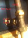
"Unique" CH/HW design with dual pumps

Joined
5 Sep 2024
Messages
6
Reaction score
0
Country
United Kingdom
I’m hoping for some advice regarding a somewhat “unique” heating system, but appreciate this might be a bit of an odd one!
I’m familiar with S plan, Y plan, even W and C plan. This is not that...

Essentially it is an non-condensing traditional heat only oil boiler (no internal pump) with four tapping ports on the water jacket.

Two of those boiler ports are used for CH flow and return, circulated by one pump which feeds an open vented UFH system (that’s probably a topic for another day).

The other two boiler ports go around the water cylinder, circulated by a second pump.
It’s not a converted gravity system, just a straight loop.

I suppose a bit like a pump plus system, but made from two entirely separate pumps directly from the boiler.
No NRVs. No motorised valves. Pumps are controlled via relays.

It has been in for long while, and obviously works as far as stuff gets hot. But it has some issues on the CH side.
Ripping it all out and starting from scratch isn’t an option, but some amendments are going to have to be made.

My question is, I know it is unconventional, but are there any glaringly obvious problems with leaving the HW part of the system as it is?
I was wondering if the boiler itself will act almost like a low loss header to provide sufficient hydraulic separation between the pumps?
 
Sponsored Links
It should act as a LLH.
Are the pump relays controlled by a cylinder stat and a CH stat?,. does the UFH have a pump and thermostatc mixing valve on its manifold ?
 
Yes I believe thats how the stats work, but I'm still working through the wiring side of it.
The controller is a CentaurPlus C27 which I think has mainly been just used as a timeclock as the CH stat is located in a cold hallway and never used, which isn't ideal either.

No additional pump on the UFH manifold, just the one CH pump for the entire system. It is not a conventional UFH setup either.
Basically a homebrew manifold made of T pieces and ball lever valves, no flow meters or anything like that.
That's something I would like to change.

The biggest problem with it is corrosion issues, which I suspect is down to being a vented system, with no barrier pipe and pumps being on the return pipes.

I’d like to move the CH pump to the neutral point and change the manifold to see if that helps.
I’m pragmatic and know it is far from an ideal or efficient system, but I’m just trying to improve what is there with the minimum disruption.

If it is feasible to leave the HW part of it as it stands that would save one headache but obviously not if it is going to cause more further down the line.
 
A rough sketch of the system would be useful, especially showing the vent/cold feed arrangement, and the position of the pumps etc. I have a 53 year old oil fired S plan system with some rads greater than 40 years old and pretty sure that at least some of the pipework is non barrier, its a combined vent and cold feed and the water is perfectly clean even though only the odd drop of inhibitor has been added over the years, the circ pump is pumping into the boiler return and the vent is carried on up from the T off into the cylinder coil top (flow), the cold feed is then fed directly into the vent, below.
 

Attachments

  • Combined Cold Feed & Vent. rev1.JPG
    Combined Cold Feed & Vent. rev1.JPG
    37.8 KB · Views: 14
Sponsored Links
What you are describing is a fairly common system on older oil boiler systems.
What make/model is your boiler? Picture would be useful.
In truth with that type of system your boiler could easily be towards the end of its useful life.
 
Thanks for the replies, I've attached a simplified diagram of the system as far as I can ascertain at the moment. I'll apologise in advance, it was just a quick sketch!

CHHW.jpg


I've had to make some assumptions as a lot of this stuff including all the heating manifold is buried inside walls and cupboards so it will take quite some time to trace.

A - is a pipe labelled HW bleed in the loft, I'm assuming this is a vent from the HW tank as it is a vented tank.
B & C, looks to be how the vent and feed are connected but very difficult to tell.

I'm pretty sure you can see some issues already, but it is worth noting B & C are not likely not within 150mm.
* A & B are just poked into the top of the FE tank.
* FE tank sits on top of CW tank.
* Yes that is how the overflows are connected.

* System was installed as part of a self build/renovation by them.
I've spoken at length with them but they can't remember how they installed any of it or where anything goes.

* Its been in approx. 30 years, but altered several times in that period including moving HW cylinder downstairs and boiler and pumps outside to a new plant room.
* Piped almost exclusively in Hep2O. 22mm to manifold, 15mm loops for UFH.

* System does seem to heat rooms and HW fine (or did before boiler failed).

* The system is on either boiler #3 or #4, all failed due to water jacket corrosion. System was filled with inhibiter.
Old one has just been removed and new one is a Mistrel KU2 20-26kw.

I think it’s fair to say the CH system is likely going to need some work, but if the HW side is mainly OK that would be a start at least!

Thanks for your help.
 
Do you think the cold water might be teed in between the various UFH returns?
Re the corrosion, what are the boiler flow/return temps on CH only?, are you getting vent pump over/air ingress or/and is the F&E cistern warm/hot?, if not can you get someone to start the boiler/pump(s) while you watch for any spurt of water from the vent and watch again when someone stops them, do this for both system, and both together, if you hold a "glass" of water with the vent immersed in it, does the level go down, do this test with either & both systems.

What is the CH problem?, is it only happening when both systems are running?, if so, it shouldn't be too difficult, with the addition of a extra relay to have hot water priority where the CH will not run if the HW is also calling
 
Last edited:
Low temperature that UF heating needs to run at could lead to corrosion in the main heat exchanger. The blending is normally carried out at the UF manifold with boiler running at reasonable higher temperature.

BTW, cylinder vent goes to CWC not F&E
 
Do you think the cold water might be teed in between the various UFH returns?
Possibly, very difficult to say without dismantling things further, may also be teed into the feed side.
All I can say for certain at this stage is it goes somewhere in the vicinity of the manifold.

Re the corrosion, what are the boiler flow/return temps on CH only?, are you getting vent pump over/air ingress or/and is the F&E cistern warm/hot?, if not can you get someone to start the boiler/pump(s) while you watch for any spurt of water from the vent and watch again when someone stops them, do this for both system, and both together, if you hold a "glass" of water with the vent immersed in it, does the level go down, do this test with either & both systems.

The temperatures have never been measured as far as I'm aware. Circulators are Grundfos UPS2 15-50/60
It did used to pump over quite violently, I believe it hasn't done it so much since the last alteration where the boiler was moved outside.
However worryingly some mention was made of "sealing off the vent to stop water coming out", although I can't see any evidence of that at the moment.

System is currently drained down while the new boiler goes in - but I can certainly test when it is refilled.

What is the CH problem?, is it only happening when both systems are running?, if so, it shouldn't be too difficult, with the addition of a extra relay to have hot water priority where the CH will not run if the HW is also calling

The only real issue is replacing the boiler and towel rails (teed off a UFH loop) every few years, other than that it does heat and provide hot water fine.

Low temperature that UF heating needs to run at could lead to corrosion in the main heat exchanger. The blending is normally carried out at the UF manifold with boiler running at reasonable higher temperature.

BTW, cylinder vent goes to CWC not F&E

No blending on this, it is just two banks of tees, one for feeding the UFH loop and the other for the return, which is then circulated around the boiler. I don't think the UFH does run at a lower temperature in this case, at least not intentionally.

Cylinder vent should, but doesn't.
No idea why, I think probably because the FE tank is on top of the CW tank, so it was easier.
 
What temperature is the boiler stat set to, that will give a fair idea of its flow temperature, was the present boiler condensing or non condensing?, presume the new one is condensing.
The jacket failure may be due to the return temperature being too low, 45/50C is normally the minimum for kerosene fired condensing boilers,
THe vent can/should only be blanked if the cold is I think 22MM, you could fairly easily convert it to my system, just cut the cold water close to the F&E, and T it in to the vent, you can then (at least temporarily) just put a blanked compression fitting on the cold down pipe so can easily reverse the modification, if required, would also suggest installing a manual air vent at the cylinder coil top connection while the system is now drained down.
 
Looked to be set to around 60 degrees. Old boilers were non condensing, new one is also non condensing.

I think there was a lot of oxygen in the system, could a lot of that be down to the CH pump on the return putting the system under negative pressure?

I did think it would probably need some sort of vent on the HW loop, tank is still sitting slightly higher than the boiler.
 
Looked to be set to around 60 degrees. Old boilers were non condensing, new one is also non condensing.

If the dT through the CH system is 20C then the possibility of a return temp of 40C, may be a problem, you can buy a clip on thermometer and clip it on the return, close to the boiler


I think there was a lot of oxygen in the system, could a lot of that be down to the CH pump on the return putting the system under negative pressure?

I dont think installing the pump(s) on the boiler flow on its own will make any real difference as the pressure drop through a oil fired boiler is negligible, a few ins WG., if you do reposition it then you could install the traditional VCP system, from the boiler, Vent, Cold feed, (no more than 150MM "away"), and Pump, however this means running two independent pipes which even then might not cure the problem, the combined vent and cold feed works in 99% of cases even where the VCP system hasn't.

I did think it would probably need some sort of vent on the HW loop, tank is still sitting slightly higher than the boiler.
 
No blending on this, it is just two banks of tees, one for feeding the UFH loop and the other for the return, which is then circulated around the boiler. I don't think the UFH does run at a lower temperature in this case, at least not intentionally.
Looking at your drawing, the pump could be pumping over. There may in some cases be a spurt of water at pump start or continuous discharge from the vent pipe. a visual of this will be possible at pump start and if pump speed is increased. Pumps used to be located on the return in olden days but now does not matter

Underfloor pipe has a foil barrier so protected against air ingress through the pipe wall. Some plastic pipes for hot and cold services do not have a foil barrier and this type of pipe is to be avoided for central heating use. There is a brown pipe called Bartol this is really bad for air ingress.
 
Looking at your drawing, the pump could be pumping over. There may in some cases be a spurt of water at pump start or continuous discharge from the vent pipe. a visual of this will be possible at pump start and if pump speed is increased. Pumps used to be located on the return in olden days but now does not matter

Yes the system used to violently pump over, but I understand this has reduced since the pump and boilers were moved.

Underfloor pipe has a foil barrier so protected against air ingress through the pipe wall. Some plastic pipes for hot and cold services do not have a foil barrier and this type of pipe is to be avoided for central heating use. There is a brown pipe called Bartol this is really bad for air ingress.

This was all done in the original non barrier grey Hep2O plastic pipe for all CW, HW and CH loops.
 
Yes the system used to violently pump over, but I understand this has reduced since the pump and boilers were moved.
Issue will still be there as configuration in the picture has resolved nothing.
For a start, point C needs to be between the pump and the boiler.
 

DIYnot Local

Staff member

If you need to find a tradesperson to get your job done, please try our local search below, or if you are doing it yourself you can find suppliers local to you.

Select the supplier or trade you require, enter your location to begin your search.


Are you a trade or supplier? You can create your listing free at DIYnot Local

 
Sponsored Links
Back
Top