Upgrading from LP241 to Nest 3rd Gen

Joined
27 Aug 2024
Messages
8
Reaction score
2
Country
United Kingdom
Hello.

I know this question has been asked many times but I would just like to clarify a few things before my new thermostat arrives.

My setup:
I believe I have a Y plan system (a 3 way valve is located in the airing cupboard upstairs along with the pump and 'wiring centre'. The LP241 is located in the kitchen about 2 meters from boiler and the thermostat is in the hallway, ~2 meters from LP241.

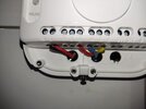
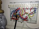
Here are some pictures of my current setup (I am not responsible for the existing installation!)

LP241:
IMG_20240827_233027.jpg

IMG_20240827_233613.jpg

IMG_20240827_233623.jpg

IMG_20240827_233646.jpg

Note the 'interesting' way the L wire is connected ^

Wiring Centre:
IMG_20240827_232622.jpg

IMG_20240827_232633.jpg


Thermostat:
IMG_20240827_232857.jpg

IMG_20240827_232744.jpg


Initially I believed the wiring to the LP241 is wired to the nest as follows:

LP241Nest Heat Link
NN
LL
1 (HW OFF)4 (Hot Water Satisfied)
2 (CH OFF)1 (Heating Satisfied)
3 (HW ON)6 (Hot Water Call-for-heat)
4 (CH ON)3 (Heating Call-for-heat)

Additionally a link is needed between Terminals L, 2 & 5 on the Heat Link.
Screenshot 2024-08-27 235317.png


But why is nothing connected to Pin 2 of the LP241?

I was hoping I could power the nest thermostat from existing wiring utilising terminals T1 & T2 on the Heat Link, but I don't think this is possible. It isn't immediately obvious to me how the system operates.

If anyone could help me out it would be greatly appreciated.

Regards

Stuart
 
Last edited:
Sponsored Links
Am I right in thinking the CH OFF wire is not needed because without a call for heat the CH is off (either from the LP241 or an 'open' thermostat)

If true, can terminal 1 on the heat link have nothing connected to it?
 
But why is nothing connected to Pin 2 of the LP241?

I was hoping I could power the nest thermostat from existing wiring utilising terminals T1 & T2 on the Heat Link, but I don't think this is possible. It isn't immediately obvious to me how the system operates.

It depends on the requirements of the heating system components. Terminal 2 isn't used because the Mid Position valve doesn't need it. It knows where to position itself using the CH ON / HW ON and HW OFF. [Many installations don't use terminal 1 HW OFF either, but yours does]

T1 and T2 at the Heatlink connect to T1 & T2 at the Nest thermostat. You can use the old thermostat wiring, but it must be completely disconnected from the mains as T1 & T2 are only 12v.

This can be done by disconnecting the existing room thermostat cable completely at both the thermostat and wiring centre ends. At the wiring centre end, a link must be inserted between the terminals that the red and yellow wires are removed from to complete the circuit. Once the cable has been completely disconnected from the mains wiring, it can be used for the T1 & T2 connections.

By the way, the original installer hasn't stuck to the lid nomenclature when wiring the system up, which isn't that unusual. So it will be necessary to identify any wiring by what's on the other end of it, not what's printed on the lid.
 
But why is nothing connected to Pin 2 of the LP241?
. It isn't immediately obvious to me how the system operates.
There's a good introduction to how Y plan systems work here...


Initially I believed the wiring to the LP241 is wired to the nest as follows:

LP241Nest Heat Link
NN
LL
1 (HW OFF)4 (Hot Water Satisfied)
2 (CH OFF)1 (Heating Satisfied)
3 (HW ON)6 (Hot Water Call-for-heat)
4 (CH ON)3 (Heating Call-for-heat)

Additionally a link is needed between Terminals L, 2 & 5 on the Heat Link.
Yes, that would be correct, excluding terminal 1; heating satisfied is very rarely used.
If you intend to use T1 an T2 to power the thermostat, you would also need an earth connection to the HeatLink earth terminal.

I believe the cable to the LP241 is hiding behind other wires in the wiring centre - I think this is the cable to your existing thermostat, could you confirm?
Screenshot_20240828-084234_Chrome.jpg

If so the red wire coming from the left of the image in terminal 10, would be moved to join the white wire in terminal 9, bridging out the old stat.

The cable could then be reutilised for T1 and T2, but you would still have to find a neat way of getting another cable from the HeatLinks new location, back to the wiring centre (to join up with the old thermostat cable).

...and beaten to it by @stem :)
 
Last edited:
Sponsored Links
T1 and T2 at the Heatlink connect to T1 & T2 at the Nest thermostat. You can use the old thermostat wiring, but it must be completely disconnected from the mains as T1 & T2 are only 12v.

This can be done by disconnecting the existing room thermostat cable completely at both the thermostat and wiring centre ends. At the wiring centre end, a link must be inserted between the terminals that the red and yellow wires are removed from to complete the circuit. Once the cable has been completely disconnected from the mains wiring, it can be used for the T1 & T2 connections.
Thank you stem.

Unless I not understanding this correctly I don't think I have enough spare wires to power the nest with T1 & T2.

Would it be possible to put a 240V>12V power supply next to the wiring centre and use 2 wires that go to the existing thermostat to power the nest?

Routing a cable between the heat link and the thermostat is not an easy "clean" job

I really should have changed the thermostat when we decorated the kitchen, but oh well.
 
Unless I not understanding this correctly I don't think I have enough spare wires to power the nest with T1 & T2.
You wouldn't have any spare wires in the current LP241 location.
The alternative would be to site the Heat link next to the wiring centre and decommission the LP241 wiring.
 
You can use the existing thermostat cable as below where it runs from the old thermostat. You might have to extend it at the other end to reach the Heatlink though.

It would be good to make the link anyway to decommission the old thermostat properly, if it was left in circuit it could end up interfering with the operation of the Nest.

123.jpg


Nest can supply a plug-in PSU for the thermostat. I've never used a non Nest power supply, others on the forum claim to have done so in the past, and say that it works satisfactorily. It needs to be DC and I would imagine also smoothed and stable to avoid damaging the electronics.
 
I believe the cable to the LP241 is hiding behind other wires in the wiring centre - I think this is the cable to your existing thermostat, could you confirm?
Screenshot_20240828-084234_Chrome.jpg
The cable you circled is indeed what goes to the thermostat

I confirmed this by connecting the blue and red wire together at the wiring centre (power isolated at the fusebox) and then did a continuity check at the thermostat and got a satisfying beep.

I have noticed that the wiring centre is not permanently live, so my plans of adding a 240V>24VDC power supply won't be so easy. There are nearby sockets that I will be able to spur off. I'm not entirely sure if what I'm suggesting is 'legal'

It would be good to make the link anyway to decommission the old thermostat properly, if it was left in circuit it could end up interfering with the operation of the Nest.

123.jpg
Is that what you mean? Adding link wire between terminals 9 & 10? (obviously after removing yellow from terminal 9 wire and the rightmost red wire from terminal 10)
Screenshot 2024-08-28 131841.png


What does this link wire do?

Edit: I thought it might be useful if I added an extra picture of the thermostat wiring I found inside the thermostat cover:
IMG_20240828_133212.jpg
 
Last edited:
The thermostat has a contact (switch) inside that opens and closes. This is it:

456.jpg


When the contact is closed, the red and yellow wires are electrically joined together and the heating comes on. When the contact opens the wires are no longer connected and the heating goes off.

If the thermostat was just removed and there isn't a link added, electrically speaking it would be exactly the same as the thermostat being 'off' and the heating won't operate, ever. Inserting the link completes the 'open circuit' and allows the Nest Heatlink to take over sole control of the heating.

The link you've shown in green is correct.
 
The thermostat has a contact (switch) inside that opens and closes. This is it:

View attachment 353763

When the contact is closed, the red and yellow wires are electrically joined together and the heating comes on. When the contact opens the wires are no longer connected and the heating stops.

If the thermostat was just removed and there isn't a link added, electrically speaking it would be exactly the same as the thermostat being 'off' and the heating won't operate, ever. Inserting the link completes the 'open circuit' and allows the Nest Heatlink to take over sole control of the heating.
So obvious! Thank you stem!
 
It is when you know. :giggle:

Instead of the link you could of course simply put the remaining white and red wires currently in terminals 9 & 10 together in one of the terminals, which achieves the same thing.
 
I have noticed that the wiring centre is not permanently live, so my plans of adding a 240V>*24VDC power supply won't be so easy.
Looking at your wiring centre, I think terminal 8 may be a permanent live.
But as I said earlier, it's a little difficult to tell, with the LP241 cable hiding.
*12VDC :)
 
So, the Nest thermostat arrived today and I wired it as above. However it is not working at all. The nest is clicking on but the boiler is firing. The only changes I have made to the wiring centre is removing the 4 wires that went to the thermostat and moving the remaining red wire in terminal 10 to terminal 9 to link out the thermostat.

Here is the wiring of the heat link:
17251186447298947698255441811075.jpg

And the wiring centre:
17251188726341975349652497656376.jpg

Note: I utilised terminals 14 & 15 to provide 12VDC and wired the red and blue wires that went to the old thermostat to power the nest thermostat.

I'm a bit stumped...

Edit: it's probably worth pointing out that exposed wires in the wiring centre (which are the remaining 2 wires used for the old thermostat) are isolated. I plan to trim the exposed copper, tape and label them. I'd rather keep them than cut them off completely.
 
Last edited:
Add short link wires between L, 2 and 5 in the Heat Link.
And just to tidy up, park the loose thermostat wires in a spare terminal - you don't want them touching something they shouldn't.
 
Add short link wires between L, 2 and 5 in the Heat Link.
And just to tidy up, park the loose thermostat wires in a spare terminal - you don't want them touching something they shouldn't.
DOH! I even wrote that in my first post. How did I miss that?!?

I'll add and report back (and show my tidier wiring centre wiring
 

DIYnot Local

Staff member

If you need to find a tradesperson to get your job done, please try our local search below, or if you are doing it yourself you can find suppliers local to you.

Select the supplier or trade you require, enter your location to begin your search.


Are you a trade or supplier? You can create your listing free at DIYnot Local

 
Sponsored Links
Back
Top