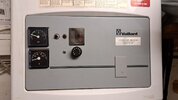
Vaillant GB VC112e fit smart thermostat

Joined
26 Nov 2024
Messages
4
Reaction score
1
Country
United Kingdom
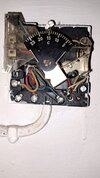
Got this boiler currently connected to an ACL lifestyle lp241 without a junction box and to an old Satchwell Thermostat.

I have purchased a Ketotek ktf0155c which I have wired into other boilers at our local community centre and working perfectly, but wanting to clarify the connections to this boiler. Would I connect it using the dry contacts?
 

Attachments

  • 20241112_131426.jpg
    20241112_131426.jpg
    158.9 KB · Views: 31
  • 20241118_152100.jpg
    20241118_152100.jpg
    244 KB · Views: 33
  • 20241118_201210.jpg
    20241118_201210.jpg
    222.4 KB · Views: 31
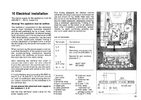
  • Vaillant-VC112E-wiring.png
    Vaillant-VC112E-wiring.png
    376.3 KB · Views: 25
  • Vaillant-VC112E.png
    Vaillant-VC112E.png
    611.3 KB · Views: 25
  • KETOTEK_KTF0155_Smart_Thermostat_Instruction_Manual.pdf
    3.5 MB · Views: 5
Sponsored Links
Do you intend for the LP241 to stay in place, and simply swap out the Satchwell thermostat for the ktf0155c?

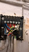
...and I'm afraid the way the earth wires are twisted together behind the LP241 needs sorting out immediately. These need to be connected together into a single terminal block - either a separate block, or clean up and find a screw for the earth terminal on the LP241 backplate.
 
The boiler only does heating, so probably no point in keeping the LP241. I'm actually thinking to replace it with a wiring junction box (https://www.toolstation.com/honeywell-home-10-way-junction-box/p51416) so the wires can be connected more safely.

Thanks.
That's a good idea.
I was trying to work out what was going on behind the LP241, but a lot of the wires just appear to be linking out the HW controls?
Do you have any zone valves in the system.

Would I connect it using the dry contacts?
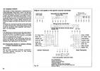
If you are totally removing the existing controller, stat, wiring, and there are no other complications like zone valves; then yes, the dry contacts would connect to boiler terminals 3 and 4.
 
Sponsored Links
The white sheathed flex goes to the boiler and only uses:
Red - L
Blue - N
Earth - E
White - 3

The 3 grey sheathed flexes go to mains, thermostat and possibly a valve, but I haven't been able to check that. The boiler manual mentions 2 or 3 port motorised valves.
 
Last edited:
That red is going to terminal 3.
Thanks.
The wiring behind the LP241 seems truly bizarre!

The LP241 is a dual channel programmer with a standard layout...
Screenshot_20241126_233128_Adobe Acrobat.jpg

There appear to be two red link wires that join L, with terminals 1 and 2.
This is odd, but not a big problem. HW off and CH off, aren't used in many systems.
In this case they will remain permanently live.

We can ignore the second cable from the left - this appears to be a red & black, twin and earth that is providing the incoming power to L and N.

The white sheathed flex goes to the boiler and only uses:
Red - L
Blue - N
Earth - E
White - 3
I believe the red is a brown and the white is really a grey, but that isn't important.
The grey wire connects to terminal 4 on the LP241 - this is the CH on terminal.
As soon as CH is timed on the LP241, the boiler will fire, the thermostat is bypassed.

If the 2nd cable from the left (with the red, yellow and blue wires), is the cable to the thermostat, then the red wire (and hence the stat) receives power when H/W is turned on.
When the stat operates, the yellow wire is a switched live, and that connects to the grey wire on terminal 4; completing the circuit and firing the boiler.

The 3rd cable from the left is another red & black, twin and earth.
The red wire is connected to a permanent live, the black wire appears to be connected to HW on.
There does not appear to be a neutral connected to this cable, so it can't power anything like a pump, or a valve; although it could be something like a tank thermostat, or another switch.

So from what I can gather. If CH is turned on by the LP241, the boiler fires and remains on without any stat control.
If HW is turned on, but CH is off, the stat becomes operational, and turns the boiler on, when the stat calls for heat.
If CH and HW are both off, if the 'switch' (or whatever it is), on the third wire closes, then the black wire on terminal 3 would become live. This brings the stat into operation and turns the boiler on when the stat calls for heat.

I may be completely wrong in my interpretation, but I haven't seen anything like this before; it would be interesting to know what is connected to the third wire from the left!
 
Last edited:

DIYnot Local

Staff member

If you need to find a tradesperson to get your job done, please try our local search below, or if you are doing it yourself you can find suppliers local to you.

Select the supplier or trade you require, enter your location to begin your search.


Are you a trade or supplier? You can create your listing free at DIYnot Local

 
Sponsored Links
Back
Top