- Joined
- 6 Oct 2024
- Messages
- 2
- Reaction score
- 0
- Country

Hi Everyone,
Long time lurker, first time poster.
I'm trying to upgrade the heating controls for my mother's boiler, it's probably 30 years old and needs upgrading itself but that is a later task.
At the moment I'm upgrading it from a timed hot water and heating, to thermostatically controlled heating. To confirm this IS A GRAVITY HOT WATER system and pumped central heating.
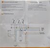
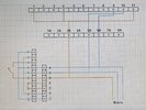
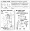
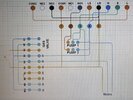
The part I am totally confused about is how to wire the thermostat (reciever) up. I have included wiring diagrams from both the boiler manual as well as the manual for the reciever and finally what I have been able to confidently wire up so far. I also have purchased 25m of 5core central heating flex so I have 5 colours to choose when wiring, (Blue, Brown, Yellow/Green, Black, Grey) - I know this won't match the diagrams but just to bear in mind if i need to double it up for more cores.
I have two pumps that need to be wired in paralel to the A terminal block (2A and 6A???, can you confirm this is correct?) I can follow a wire diagram but i'm not sure what it is, I just can't get my head around these two and how to wire them up.
To try and simplify things I have added letters to the other terminals, so for instance connection needs to be made from 3 > 1A > 3B.
Thanks in advance
B&B


