4 ceiling roses - one switch. Add Switch for one light

Ok... wow - thanks for the interest in my post.

Nothing like a healthy debate - I see you two have previous!

Some more images:-

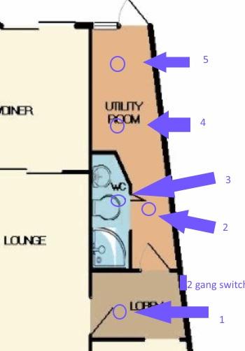
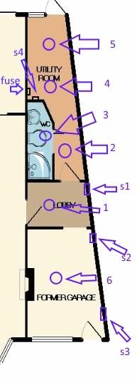
1st - the layout of pendants and switches


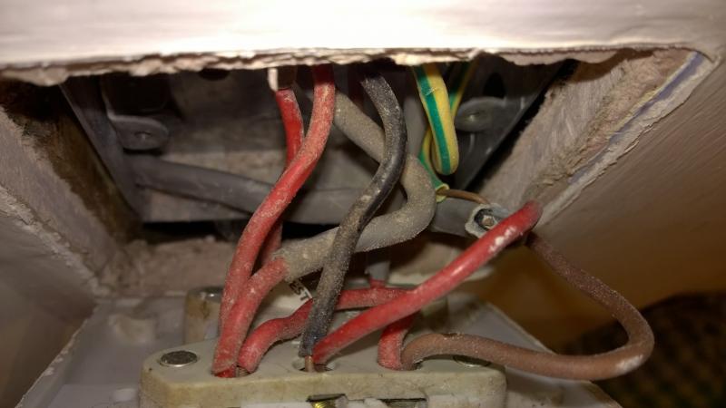
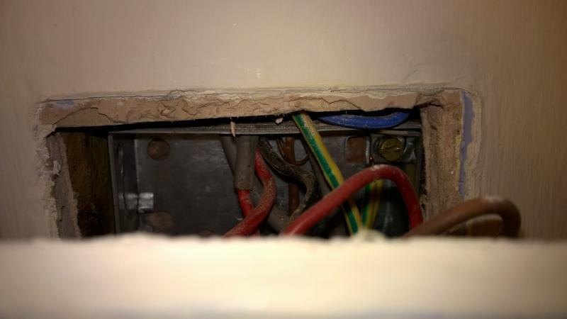
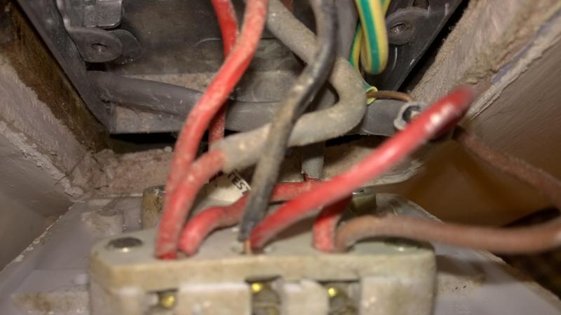
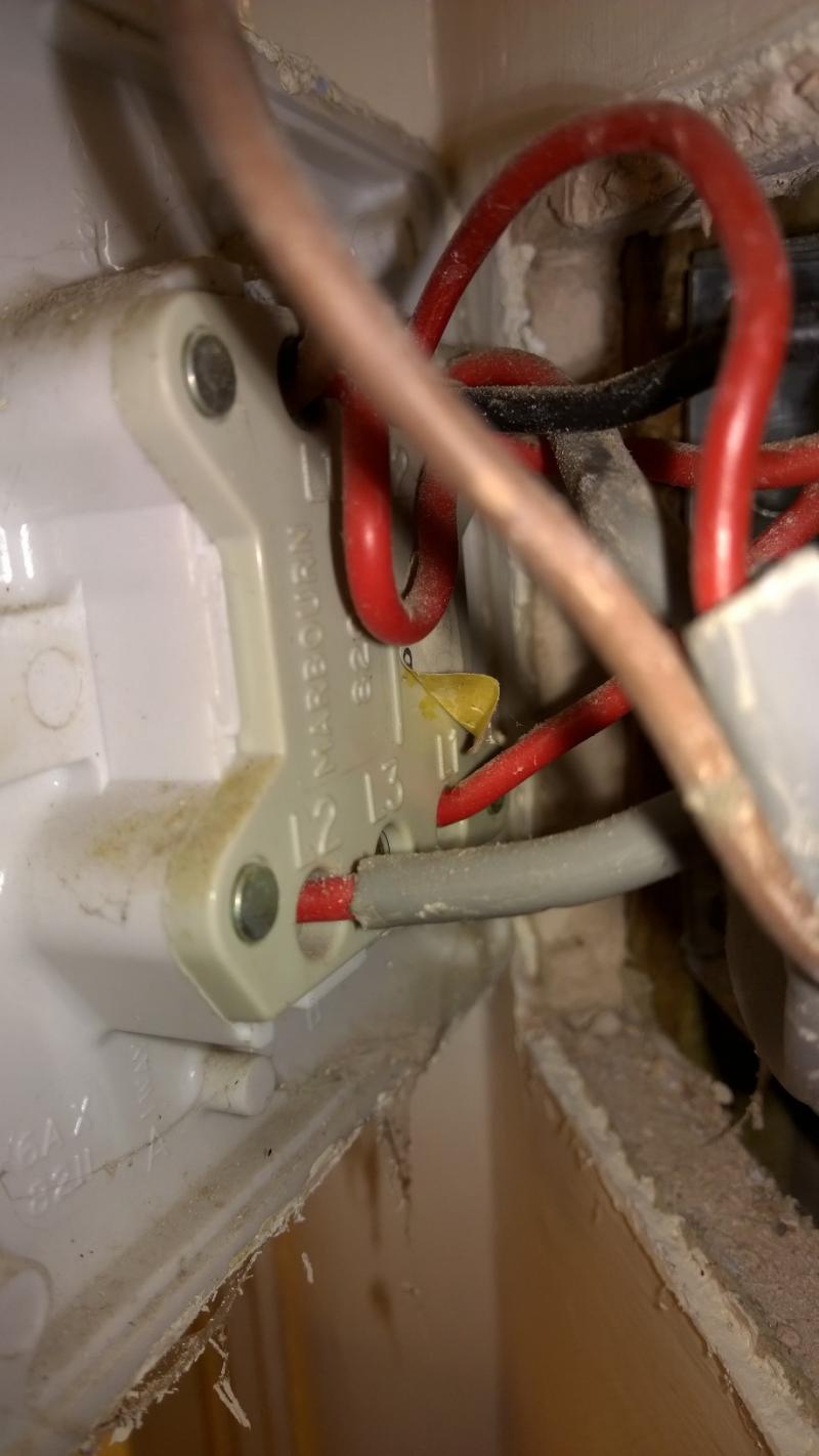
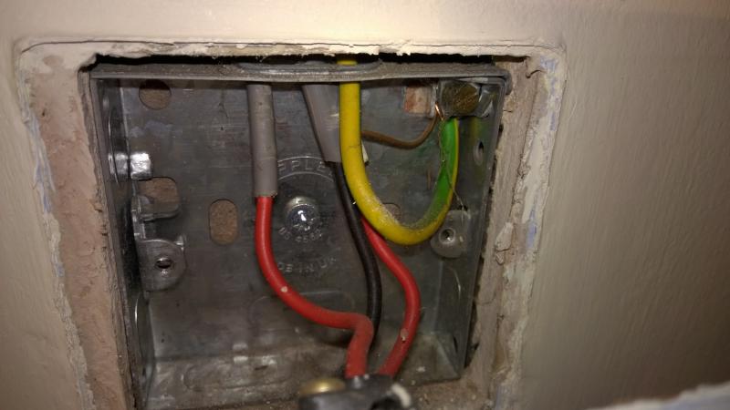
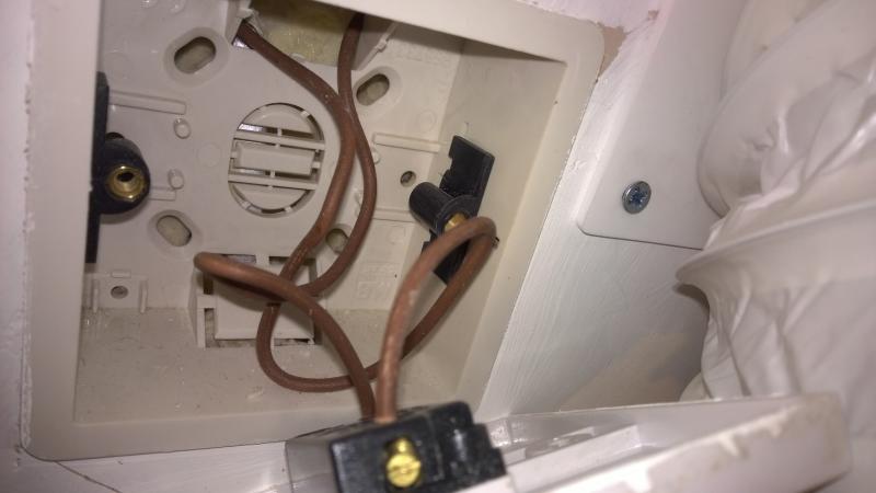
2nd - the wiring to the switch (various angles) I noted the sneaky blue...


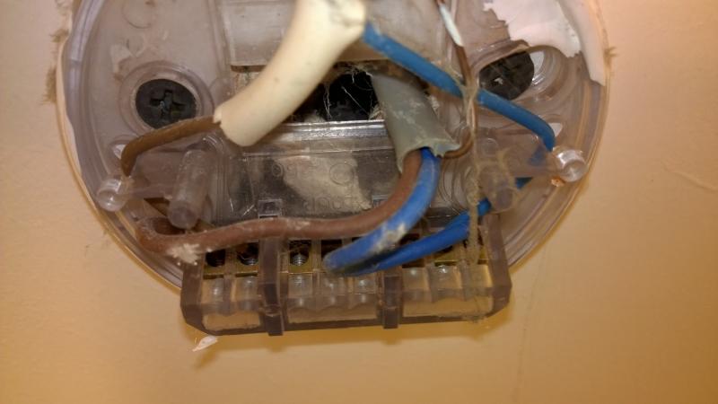
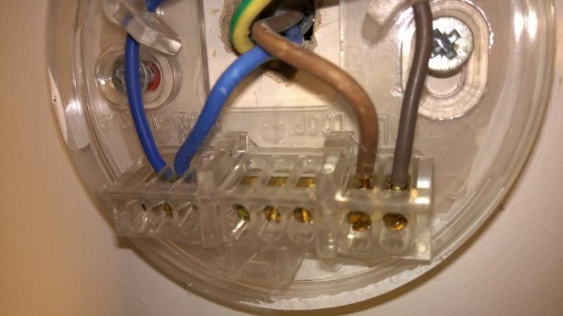
3rd - Pendant 2 (from the plan)


4th - Pendant 3 (from plan) you have seen this pendant before, but this is a new image.


5th - Pendant 4 (from plan)


6th - Pendant 5 (from plan)


Your thoughts and comments would be appreciated.

Just to repeat the objective - operate pendant 3 independently to the current switch, ideally with a new pull switch in bathroom.

Thanks.
 
Sponsored Links
doesn't look very hopeful.

One other thought: you could wire the present switch so its on all the time,
and then fit 2 (or more) new pull switches.
 
I think you need to find out how you can run a new cable into the bathroom.

Either up from the floor, or thru from the lounge etc.
 
That was my initial thought before I came onto this site....
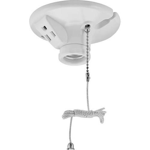
Reduce switch to one gang - have left hand permanently switched on and blanked off.


Something like this:-


Not very elegant though... and so far I have only found in the states.

*edit

I should point out - I know separate pull switches available uk.....
 
Sponsored Links
There really is only Plan A or Plan B:

PLAN A:
  • Learn how lighting circuits are wired.
  • Get a multimeter and learn how to use it.
  • Identify which conductors are which at the switches and the light positions.
  • Check for voltage present, circuit continuity, switches working etc.
  • Connect everything up properly.
PLAN B:
  • Get an electrician.
 
Ahh don't you just love builders electrics! Simplest way to achieve what you want is as already suggested to change the current double switch for a single and wire it so the lights are on all the time. The install a new surface mounted switch inside the extension door for the 3 lights and a pull cord in the bathroom. If the roses are wired as I suspect then it should be a nice easy job for any electrician, 2/3 hours work tops!

One odd thing though is the current switch appears to be wired for two-way switching, is there any other switch that turns these 4 lights on/off?
 
Thanks for input everyone....

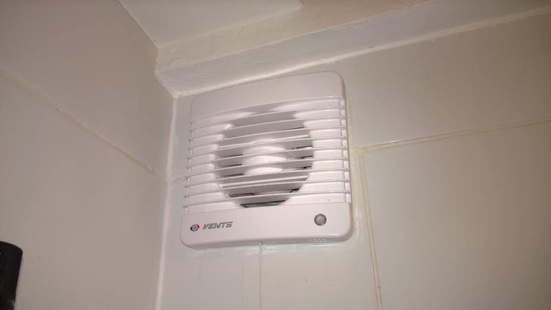
I am now aware of an added complication - an extractor fan!
(Maybe this is the elusive two way switching Dannyboi suggests?)

This is activated from the same 2gang switch - lights on (but in addition has its own switch which can switch extractor off, but lights remain with ability to switch on/off)

So maybe somehow utilise this??

I have pics, but didn't have time to remove some faceplates - so to avoid the wrath of BAS (yes, well aware pics of faceplates/light fittings do not give you an indication of wiring, my first images were for locations/relationships)

I will post tonight.

Thanks for the suggestions, possible solutions, and ideas of work involved for electrician (which gives me an informed choice, and idea what I may be charged)

More to follow.....
 
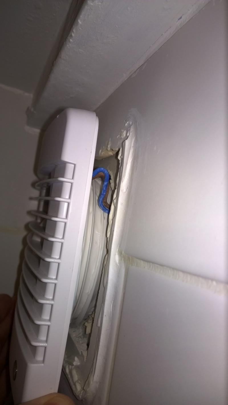
Hmm no that doesn't really account for the two-way switch wiring, it looks like there was another switch at some point, maybe further clues will be revealed when we see the extractor fan wiring, in your double switch there is a newer brown cable and a blue one hidden just above, that could be something to do with the fan.

If its not too much trouble, the other light that switch controls (the right hand switch) can you open the rose on it and take pics of how its wired?

Thanks
Dan
 
Ok, back with some pics.

Dan you were spot on there is another switch that controls the four lights.

To make sense of everything - please see revised plan, this time of the full extension (Including original garage)


Key (most as before)

1. Pendant 1 controlled from s1 switch right hand side and s3
2. Pendant 2 controlled from s1 and s3
3. Pendant 3 controlled from s1 and s3 (This is the one I want t o control independently, but also initiate the fan)
4. Pendant 4 controlled from s1 and s3
5. Pendant 5 controlled from s1 and s3
6. Pendant 6 controlled from s2 (its a dimmer switch)

s1 - 2 gang switch (left controls pendant 2,3,4,5 + extractor, right controls pendant 1)
s2 - dimmer controls pendant 6
s3 - 1 gang controls pendant 2,3,4,5 + extractor

s4 - 1 gang switch controls power to fan in wc (pendants still work if off)

Fuse - 3 wires as image (I have not opened)
Below fuse is another switch - this is for external security light.

Extractor fan images:-


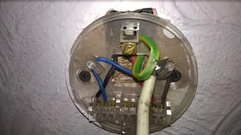
Pendant 1 as requested:-


s3 :-


s4:-


Fuse:-


General location fuse, s4, security light switch


I hope that sheds some light on my problem....

Any advice, possible solutions etc welcome. Thanks again.
 
It definitely looks a builder's or DIY'ers job.

Personally, not that there's anything wrong with the black bugle head drywall screws, but I wouldn't use them to fix accessories. But a builder or DIY'er would.

It would appear that S1 and S3 could possibly have started out as the existing switch positions for the old garage?

As for the wiring from the switches, it would appear there are plenty of singles and double insulated singles in the switches that are live loops and the neutrals appear looped at the ceiling positions. But there must be the odd sneaky junction box somewhere, because I have trouble adding this lot up logically:

Luminaires 2, 3 4, 5 and the fan are all wired together.

Luminaires 2, 4 and 5 all have a single feed in (RB in 5's case). 5 also has what appears to be just a neutral leaving the rose in a twin and earth.
At least, I cannot determine where the brown is terminated.
This could be for the fan?

Luminaire 3 has 3 cables entering (one of which is RB). One of these has to be the feed in. The RB could go to luminaire 5 (complete guess, I know, I know!!), but that leaves luminaire 4 without a feed, leaving me to suspect that there has to be a JB somewhere in the roofspace.

The switched feed into luminaire 3 could be junction boxed in the void and a cable run off to luminaire 4 (for example).

I know it all seem illogical from a spark's POV (certainly mine!), but I'm just trying to get into a builder's mindset!

PS Can't see any fuse in your piccys....

I'm off to take an Ibuprofen and lie down now.....
 
Any advice, possible solutions etc welcome. Thanks again.
There really is only Plan A or Plan B:

PLAN A:
  • Learn how lighting circuits are wired.
  • Get a multimeter and learn how to use it.
  • Identify which conductors are which at the switches and the light positions.
  • Check for voltage present, circuit continuity, switches working etc.
  • Connect everything up properly.
PLAN B:
  • Get an electrician.
 

DIYnot Local

Staff member

If you need to find a tradesperson to get your job done, please try our local search below, or if you are doing it yourself you can find suppliers local to you.

Select the supplier or trade you require, enter your location to begin your search.


Are you a trade or supplier? You can create your listing free at DIYnot Local

 
Sponsored Links
Back
Top