I’m curious, have you measured it? How? At 600 MHz?
Yes of course I have, why else would I have mentioned the subject? I have used various kit over the years, a service monitor was always my first choice but these days I usually use a vector network analyser
hooked to a PC.
My VSWR meter is designed for 50 Ω, and I have nothing which transmits which is anything other than 50 Ω, however I have use 50 Ω coax for TV, and it is not very good. Making a HB9CV for TV is a bit hit-and-miss, again as to measure the reflected power one needs more power than one receives.
See above.
I'm surprised you say 50Ω was not very good I've not had the same experience.
However, we can play with 50 Ω and it is a reasonable assumption that 75 Ω will act similarly. We could calculate what is needed for a balum, but think highly unlikely that many without having studied for the RAE exam will have the slightest idea of what we are talking about. Yes, it was touched on when doing my degree, but all I really needed to say was splitting in the same way as a supply to a 13 amp socket does not work.
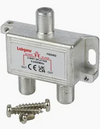
Something like this
View attachment 375922will have something inside, so the signal is shared. It is not a case of winding the wires together.
I agree, however bearing in mind the extremely poor impedances of the domestic (and for that matter some of the professional) TV based kit I personally have had no issues in my own home (I hesitate to call it an installation - see below) and I have all sorts of bits chucked in for one reason or another.
I have 10 outlets of which 7 are usually connected to a receiver and all are simply teed together, this botch started when moving in in 1994 in the days of analogue with the aerial pointing at Crystal Palace at 25 miles distant. I'd get a very minor aircraft flutter.
During building works around 2010 the aerial got badly damaged by a tarpaulin, I replaced it with an aerial I originally purchased many years ago for a previous property specifically to point at a different transmitter to receive CH5 which IIRC was on channel 65 ish so around 800MHz and as such it is a very narrow bandwidth. When moving house in 1992 I removed it as it was sharing a pole with my Amateur radio aerials. It is now low down on the chimney (below the lashing kit) and roughly pointing at a nearer transmitter, 5 miles distant, which IIRC uses all low 40's channels so possibly 100MHz below the aerials bandwidth.
It's rather embarrassing to admit this:
is one of two of my TV network joints lurking under the floorboards, the brown and white are the feed from the aerial and to the other joint, the 2 blacks are 10m ish feeding TVs, the top is 1200Ω (1.2KΩ, typical of car radio aerials), the short piece of cream is 75Ω and the bottom black is RG174 (3mmOD 50Ω).
The other joint is just the same construction and includes RG58 (50Ω), RG59 (75Ω low quality video type), RG62 (92Ω data) along with regular cheap TV coax with a hint of screening.
One of the presentation events we did included multiple flat screen TVs dotted around the hotel venue, originally we were led to believe we could hook into their UHF distribution system and even shown to the cupboard with the tuners, modulators and distribution amps and allocated a composite video input, however on the day no key could be found so we did a quick botch with ordinary twin flex looped around and teed in various combinations, it was not perfect but it got us out of a hole.
This is only TV we are talking about and now it's digital patterning is pretty much a thing of the past.

 will have something inside, so the signal is shared. It is not a case of winding the wires together.