Caravan Electrics

Joined
25 Oct 2012
Messages
496
Reaction score
11
Location
Dorset
Country
United Kingdom
Good Morning All,

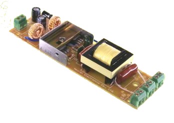
One of the lights in my caravan isnt work so i set about going to work with my multi-meter. I found i had voltage to the circuit board (pictured) but nothing coming out for the lighting terminals.

I did various resistance and Continuity checks and ive got a couple of questions about the pictures and the results i got.

When I con checked the black thing in the 4th picture (not sure what it is as i cant see any values on it, look resistory shape but obviously isnt one) it was Open Circuit. Also in the 1st and the 3rd picture, the blue things also resulted in open circuit. Im not sure what its ment to be as I can see any units of measure on there. The resistors and all other bits on the board all work fine.

Anyone think they might know why the light isnt working?

Regards

 
Sponsored Links
What's the function of this pcb? Do you have a circuit diagram?
You're unlikely to find a fault by random resistance/continuity tests.
 
I'm guessing this is a 12V fluorescent light, if so they are not that expensive to replace the fitting.
Or do away with the fluorescent bulb & fit LED
 
Hi

It is a 12v Flouresant Light. What is the unit called if i was to try and get a replacement? Also do you know what it actually does?
 
Sponsored Links
The board is an inverter, converts the 12V DC to a higher voltage for the fluorescent tube.
They can be purchased, but would probably be a similar price to a complete new light fitting.

The 'black thing' is a diode, it would measure o/c depending on what you were measuring it with and the polarity of the test voltage.
The blue objects are capacitors and would also measure o/c with a continuity meter.

It can probably be repaired, but given the very low cost of the device, it will not be worthwhile.
 
When I con checked the black thing in the 4th picture
Do you mean the diode?


it was Open Circuit
How did you test it?


Also in the 1st and the 3rd picture, the blue things also resulted in open circuit.
They look like capacitors. How did you test them?

Not every electronic component can be "tested" by looking for a low resistance path through it for DC current.


Anyone think they might know why the light isnt working?
What is that PCB supposed to do?


Doh - too slow
 
The board is an inverter, converts the 12V DC to a higher voltage for the fluorescent tube.
They can be purchased, but would probably be a similar price to a complete new light fitting.

The 'black thing' is a diode, it would measure o/c depending on what you were measuring it with and the polarity of the test voltage.
The blue objects are capacitors and would also measure o/c with a continuity meter.

It can probably be repaired, but given the very low cost of the device, it will not be worthwhile.

Thanks mate. I had a feeling they could have been Capacitors but usually you see a uF on there somewhere but there is nothing. Any ideas where i could get one?
 
When I con checked the black thing in the 4th picture
Do you mean the diode?


it was Open Circuit
How did you test it?


Also in the 1st and the 3rd picture, the blue things also resulted in open circuit.
They look like capacitors. How did you test them?

Not every electronic component can be "tested" by looking for a low resistance path through it for DC current.


Anyone think they might know why the light isnt working?
What is that PCB supposed to do?


Doh - too slow

I didnt realise it was a diode, i have a Diode test facility on my fluke so Ill check that out.

And i have no idea what the PCB does, all i know is my light wasnt working and when i unscrewed the fitting i found that connected behind it.
 
The board is an inverter, converts the 12V DC to a higher voltage for the fluorescent tube.
They can be purchased, but would probably be a similar price to a complete new light fitting.

The 'black thing' is a diode, it would measure o/c depending on what you were measuring it with and the polarity of the test voltage.
The blue objects are capacitors and would also measure o/c with a continuity meter.

It can probably be repaired, but given the very low cost of the device, it will not be worthwhile.

I tried both AC and DC at the output as i thought it could have been an inverter but still nothing but i definately have 12vDC going in on the red line.
 
I'd missed the fact that it's cnnected to a flourescent tube.
As flameport said, it's an inverter. It converts the 12V DC from the battery to a couple of hundered volts at a high frequency.
The best thing to do is to buy a new caravan light fitting. An LED will be more efficient, thereby saving a little of your battery power.

Thanks for your reply. Any ideas where i might find one. Probably go for LED.
 
I can see two transistors two coils two resistors and one diode and three devices which could be capacitors but could be something else.

So likely something like this
220px-Transistor_Multivibrator.svg.png
basic design but two resistors replaced with coils or transformers.

They have been made like this since very early days See Wikipedia but once they fail it is common for one component to take out another so to repair is like chasing ones tail.

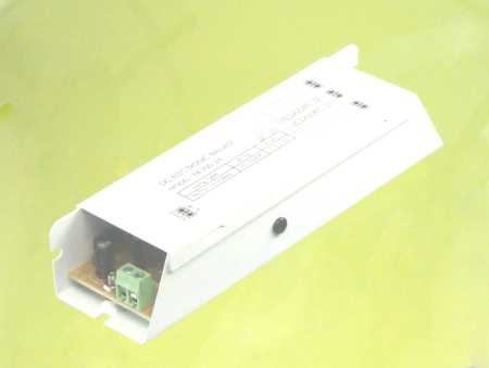
I replacement will look like this
eb-20D-12.jpg
boxed so this
ballast.jpg
is what you see and as already stated likely costs more than a complete lamp.

l108b__83533_std.jpg
the one shown has two 8W tubes and costs £9.14 however as already stated today the LED is king.

The 12 volt florescent ballast comes in two basic designs. Early models used a tapped transformer which took the AC supplied from the Multi vib and transformed into approx 7 - 80 - 7 volt once the tube fired this would drop to around 3.5 - 40 - 3.5 volt the heaters getting 7 volt at start dropping to 3.5 volt once fired up which resulted in a 8W tube taking around 12W much better than tungsten and the electronic noise was quite low but latter models did away with the heaters with a before strike voltage of around 180 volt and after strike again 40 volt this would seem more efficient but in real terms very little in it as the components ran hotter.

For the larger units there was a move to a full switch mode system so 20 W tube used 20W but even today the 8, and 16 W have a very basic design and produce loads of electronic noise as well..

To be fair the LED version is little better. There are two ways to reduce the current feeding an LED one is a switched mode power supply the other is a simple resistor the problem is looking at the spec rarely tells one which is used and although with a switched mode power supply they are super efficient with a simple resistor they are not.

Mains voltage LED's nearly always have a switched mode controller and the spec 100 volt to 250 volt is a give away as to them using an integrated circuit switch mode power supply.

But with extra low voltage (12v) it is rare to find any thing more than 12 volt nominal voltage finding one with rating 9 - 15 volt is rare. It would seem many are in fact supplied with a switched mode integrated circuit but as the user one has not a clue if the LED will work 11.5 to 14.8 volt found in a caravan with a stage charger or not.

So although LED is clearly the way to go I would tend to just replace with same as you already have as it's just a lottery as to if you get super efficient or not with LED and on balance not worth the change.

This is of course a personal opinion some may be able to point to a product they know uses the switch mode regulation and is super efficient.
 
I wouldn't bother trying to measure the output with a fluke, they are usually high frequency and flukes don't like that.
To check a diode you'll need to remove it from the board first, forward biased it should measure 0.7v and reverse biased OL.
The choke next to the diode should just read a resistance with a fluke.
Chances are, as others say, it will be cheaper and easier to replace the unit.
 

DIYnot Local

Staff member

If you need to find a tradesperson to get your job done, please try our local search below, or if you are doing it yourself you can find suppliers local to you.

Select the supplier or trade you require, enter your location to begin your search.


Are you a trade or supplier? You can create your listing free at DIYnot Local

 
Sponsored Links
Back
Top