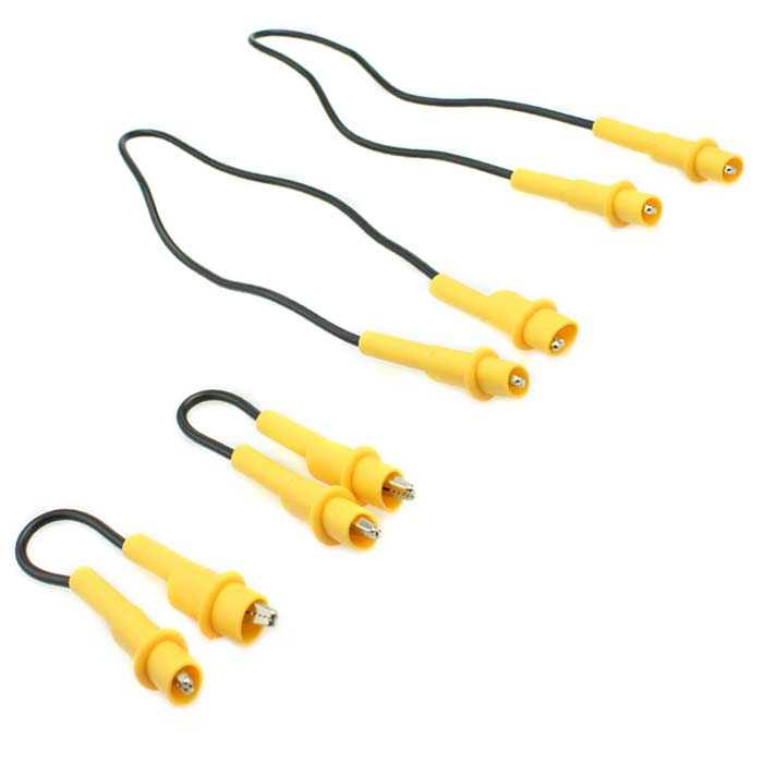
Figure of 8 tests

Joined
30 Mar 2015
Messages
4,153
Reaction score
64
Country
United Kingdom
When extending a ring final, and then testing R1+Rn and R1+R2, should this be done from the CU or a socket? Interested to know if there are any pros/cons. I’ve always done at the CU but a challenge I often encounter is that the wires are looped when removed from the terminals. This looped wire won’t slot into a wago and if I try straightening it out, it will break and sometimes there isn’t much length on the cable.

How do you connect these into a figure of 8 before going around the sockets with an MFT?

Thanks in advance.
 
Sponsored Links
When extending a ring final, and then testing R1+Rn and R1+R2,
You should use lower case 'r' for the tests. Upper case 'R' is used for the actual values of the ring when in use.

For example r1 is the resistance of the length of the line conductor; R1 is a quarter of that because of the ring formation.

should this be done from the CU or a socket?
Either.

Interested to know if there are any pros/cons. I’ve always done at the CU but a challenge I often encounter is that the wires are looped when removed from the terminals. This looped wire won’t slot into a wago and if I try straightening it out, it will break and sometimes there isn’t much length on the cable.
What is it with Wagos these days? They are not the only connectors.

If there isn't enough length, use something else.
You can get short jump leads for joining the conductors.

How do you connect these into a figure of 8 before going around the sockets with an MFT?
 
You should use lower case 'r' for the tests. Upper case 'R' is used for the actual values of the ring when in use.

For example r1 is the resistance of the length of the line conductor; R1 is a quarter of that because of the ring formation.
I think I am referring to the uppercase R for these tests. Once the figure of 8 is created at the CU, I would be walking around the sockets with my MFT to check readings. I am expecting a quarter of the lowercase r readings.

Am I using the correct “R” in this case?
 
r1, r2, rn are the resistances of each conductor in the ring, determined by disconnecting the conductors at the consumer unit or socket, and measuring resistance between the ends of the conductors, L-L, E-E, N-N
They are only used for ring circuits.

R1, R2 and Rn are applicable to all circuits and the resistance from one end of the circuit to the other for a radial.
For a ring they are approximately 1/4 of the value of the r1,r2,rn values.
 
Sponsored Links
Pros at testing from a socket you can easily tell which Live and Earth to link together, in a populated board sometimes it's more difficult to see which is which without pulling lots of cables out/about. Cons - if it's fed from an RCBO you often won't be able to do an IR test as the neutral will often require completely removing so you'll need to disconnect it at the board so if that's the case you may as well test there...
 
Cons - if it's fed from an RCBO you often won't be able to do an IR test as the neutral will often require completely removing so you'll need to disconnect it at the board so if that's the case you may as well test there...
When IR testing, don’t we need to disconnect wires from MCB/RCBO? I understood that a 500v IR will damage the MCB/RCBO. Assuming yes, presumably IT can only be done at the CU with a RFC, as else the circuit will be broken in multiple places.

I can appreciate that the figure of 8 can be done at the socket and I can see the attraction to doing that.
 
How does one test before the connection of sensitive equipment if that sensitive equipment is already connected?
 
It's tested before it's connected.

Chapter 64 is for initial verification.
The concept is that you test the cables after they have been installed, but before the accessories and other equipment is connected.
This is intended to identify situations where cables have been damaged during installation, or between first and second fix.
A further insulation resistance test is done after the installation is completed, and that would typically be done between earth and L&N connected together.

Chapter 64 does not apply to periodic inspection and testing, and it is rarely necessary or practicable to conduct insulation tests between L&N for existing installations.
 
Chapter 64 does not apply to periodic inspection and testing, and it is rarely necessary or practicable to conduct insulation tests between L&N for existing installations
Would an IR test between L&N to Earth at 250v damage any connected equipment?
 
Would an IR test between L&N to Earth at 250v damage any connected equipment?
I don't think that an IR test between L&N (joined) and Earth at any credible voltage would usually damage any connected equipment, since all the 'innards' of such equipment usually sees in the pd between L&N (which will be zero with such a test).

As far as I can see, the only possible exception (although not at 250V) would be when there are L-E and/or N-E 'filter capacitors' in the equipment, which could be damaged if they were subjected to excessive voltage (which, in practice, would mean 500V or above).

Kind Regards, John
 
No, why would it - they are close to the normal operating voltage anyway.
As you imply, even if applied between L&N, 250V DC is very unlikely to damage anything used to experiencing 230V (RMS) AC. However, we're talking (well, I think we are!!) about the situation with L and N joined together (and testing between them and earth - in which case, as I said, I can't see any credible test voltage damaging anything other than possibly input filter (L-E and N-E) capacitors.

Kind Regards, John
 

DIYnot Local

Staff member

If you need to find a tradesperson to get your job done, please try our local search below, or if you are doing it yourself you can find suppliers local to you.

Select the supplier or trade you require, enter your location to begin your search.


Are you a trade or supplier? You can create your listing free at DIYnot Local

 
Sponsored Links
Back
Top