Is there any reason a spur would have L and N transposed on the load? (Ed.)

I suggest the original light fitting was a basic bulkhead or so where the error at the switch simply wasn't noticed. moving on and the light fitting was changed by a DIYer and the error was spotted and sleeved.

Quite a simple scenario.

'course it's also possible there is a brown to CPC fault and this botch stopped the MCB tripping.
Yeah there are drill holes for an outside lamp before the one I'm changing. I thought someone just added tape rather than investigate the problem any further down the line...

....
Brown to CPC... MCB tripping. What's this and can I test for it?
 
Last edited:
Sponsored Links
It looks like the spur was wired by a professional, who made a mistake by connecting the load wires the wrong way round.
It looks like the outside light was connected by an amateur, who at least realised the live and neutral were reversed and went to the trouble to sleeve them to warn the next man.

I would connect the spur up the conventional way, and then check the polarity is then correct at the light, and if so, remove the coloured tape.
 
What's these bits about tripping things.

If there were no RCD protecting the circuit, and L/brown, were shorted to earth, then it would repeatedly trip the MCB. As a botch, someone might have remarked the brown, as blue/neutral, which would allow the circuit to work normally, without tripping the RCD. A neutral shorted to earth fault, cannot be detected by a fuse, or MCB.

The supply, versus load side of the switched spur being swapped, will make no difference, but correct it anyway. It's just a matter of easy identification, for anyone who follows on later.
 
Last edited:
Hang on..the LOAD part of the spur has L an N .. Reversed..


Am I getting this right
Not sure.

The SUPPLY is the cable from the socket and the LOAD is the cable to the light.

So according to this picture:
1726831546400.png


Weren't they the wrong way round as well?

The Supply part looks ok.. but it's been reversed by then..
Except it appears NOT to be the SUPPLY


So the SUPPLY (if that goes to the light) and the LOAD are also the the wrong way round.

1726832497560.png


Am I getting this right?
 
Sponsored Links
Yes.

It's crossed over at the load input
Still crossed over at the Supply output (but the colours look correct)

Then at the light obviously still crossed over.. So someone added tape.

...

There was speculation above about it being some sort of unofficial fix for something tripping..

..

I think I'm going to wire it correctly and see there is any sort of nonsense happening... Like breakers tripping. .


On a side note
The room it's in has a ceiling fan wired to the lighting main... That occasionally trips the main consumer unit. (Apologies I don't know the exact words for all the parts) but the room is an extension so has a separate consumer unit.

Theory one
So I was thinking maybe someone was messing about fault finding (not realising it was the fan tripping the consumer unit) and didn't put this back to correct wiring.

Theory two
The running favourite idea is that it was just a bodge in the first place. And whoever fitted the light didn't bother to investigate.

..

I just wanted to check that this is not some sort of industry standard thing that I don't know about.

..

But yeah I'm going up wire it correctly when the end of the glorious British summer weather stops flipping raining hahaha
 
It's crossed over at the load input
Still crossed over at the Supply output (but the colours look correct)
Not sure if you are understanding correctly.
Apart from the wire colours being crossed over, the supply and load are crossed over as well.
The supply is the cable from the socket and the load is the cable to the light.

As with the colours being crossed over, this doesn't really matter unless the FCU (Fused Connector Unit - the cable is the spur) has a neon warning light which would then be on all the time.

Would you please confirm for me that the cable in the FCU load terminals is the cable from the socket - i.e. actually the supply?

Then at the light obviously still crossed over.. So someone added tape.
Yes, which made it apparent something was not right.

There was speculation above about it being some sort of unofficial fix for something tripping..
Yes, a possibility.

I think I'm going to wire it correctly and see there is any sort of nonsense happening... Like breakers tripping.
Ok.

On a side note
The room it's in has a ceiling fan wired to the lighting main... That occasionally trips the main consumer unit. (Apologies I don't know the exact words for all the parts) but the room is an extension so has a separate consumer unit.
Ok.

Theory one
So I was thinking maybe someone was messing about fault finding (not realising it was the fan tripping the consumer unit) and didn't put this back to correct wiring.

Theory two
The running favourite idea is that it was just a bodge in the first place. And whoever fitted the light didn't bother to investigate.
Anything is possible.

I just wanted to check that this is not some sort of industry standard thing that I don't know about.
No, as I indicated, the regulations state that the wires must be identified; it doesn't matter what colour they actually are although obviously there is no point in doing it like yours in the first place.

Also, many times it does not really matter which way round the L and N or the colours are and an L & N printed on a switch doesn't actually DO anything. It is just about identification.

But yeah I'm going up wire it correctly when the end of the glorious British summer weather stops flipping raining hahaha
Please let us know.
 
'course it's also possible there is a brown to CPC fault and this botch stopped the MCB tripping.
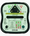
This should be soon apparent when corrected, however as far as testing goes, the problem is the cost of the meter to test it. These meters VC60B.jpgLoop impedance tester.jpgare the cheapest I could find, blue one £35 and tests installation only, red one £70 and also tests the loop impedance and RCD as well, however having them does not mean you can use them.
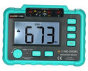
With the switched FCU turned off, testing both lives (Line and Neutral) to earth with a cheap meter on the ohms range will only show a direct short, and even a plug in tester with loop, 1726836842172.pngwill not likely show a neutral to earth fault. The problem is neutral is outside ones house connected to earth, so only way to test is with the circuit isolated, a MCB does not isolate it only turns off the line, a RCBO also normally does not isolate although some do, so the switch on the FCU or the RCD, or isolator needs turning off to test neutral to earth.
And water will often connect a wire to earth enough to trip a RCD but not enough to detect with a meter using 9 volt, the meters shown use 500 volt.

So if swapping the cables correct way around works without tripping anything then all seems good. But if it trips then likely neutral has an earth fault, which needs correcting, as it can cause what seems random tripping of the RCD. So may as well swap to correct colours, but both line and neutral are classed as live, so colours being swapped was not really a problem. It just raises the question why?
 
Thanks for all this.

There's some really great information here from everyone.

Thanks for detailed bit about the testing part too... It might be a little outside my skills....

I'll post back once I've done the wiring.

It's either going to be "smooth running" or "Herbie goes bananas*" on the consumer unit with the lights going on and off haha.. Haha..

Thanks again everyone
 
The wires coming from the socket go to the load. The wires from the supply go to the light.

Is that the information you're asking for.
 
Ok. Yikes Thanks for that.... so that's also bad... crikey..I don't know why I didn't spot that in all the goings on.

How on earth was it working wired with the supply and load the wrong way?
 
Ok. Yikes Thanks for that.... so that's also bad... crikey..I don't know why I didn't spot that in all the goings on.
Well, it's not that bad but there is no point doing it because then all the "identification" is wrong.

That is all the colours and L and N markings are - identification.

How on earth was it working wired with the supply and load the wrong way?
Because it doesn't really matter - the switch just connects two wires together; it doesn't know which is which - unless, as said, a warning light to tell you it is 'on' would be illuminated all the time.
 
I think I'm going to wire it correctly and see there is any sort of nonsense happening... Like breakers tripping. .

Always the best way..

How on earth was it working wired with the supply and load the wrong way?

It would still work, the electrons travelling through the cable care nothing for the colour of the plastic cable covering, or the markings on the switch.
 

DIYnot Local

Staff member

If you need to find a tradesperson to get your job done, please try our local search below, or if you are doing it yourself you can find suppliers local to you.

Select the supplier or trade you require, enter your location to begin your search.


Are you a trade or supplier? You can create your listing free at DIYnot Local

 
Sponsored Links
Back
Top