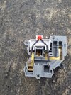
Mains indicator LEDs

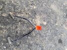
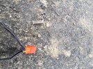
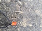
Broke one open and this is inside, looks like a neon,
If you want John give us a few weeks and I may have a few more, if you want them I could post them
 
Sponsored Links
Bg socket
 

Attachments

  • 20240813_184118.jpg
    20240813_184118.jpg
    545.2 KB · Views: 56
  • 20240813_184122.jpg
    20240813_184122.jpg
    502.3 KB · Views: 62
  • 20240813_184134.jpg
    20240813_184134.jpg
    601.9 KB · Views: 54
  • 20240813_184148.jpg
    20240813_184148.jpg
    549.8 KB · Views: 49
  • 20240813_184150.jpg
    20240813_184150.jpg
    579.9 KB · Views: 58
Well it looks like an LED with three components in series. Brave. I wonder if that fits inside the Crabtree neon space.
 
Looks like the components are encapsulated. Worth a try. I can send you some money for postage when you have two or more, thanks very much
 
Sponsored Links
It presumably is designed to be "put straight on the mains", using appropriate components and tested accordingly?
I would hope so.

It looks like a simple LED, diode and resistor. I am not sure I am confident enought to have done that but assume that BG do!
 
There must be millions of the things made every day.

Strange they are hard to find.
 
I would hope so. It looks like a simple LED, diode and resistor.
There appears to be a third component, possibly a second resistor - maybe as a 'belt and braces' measure?
I am not sure I am confident enought to have done that but assume that BG do!
Quite so. The thing is obviously designed to be connected to the mains, so I would have no concerns about doing that.
 
There appears to be a third component, possibly a second resistor - maybe as a 'belt and braces' measure?
I presume it's done to make the assembly "single fault safe", that is in the event of failure of any of the components the current is still limited to a safe level.

Using a series diode to protect an LED from reverse voltage is sub-optimal because the balance of reverse voltage between the diode and LED can be hard to predict, but I suspect that BG have decided that the risk of eventual failure in this condition is something that can be tolerated.
 
I presume it's done to make the assembly "single fault safe", that is in the event of failure of any of the components the current is still limited to a safe level.
Indeed - that's what I meant by #blet and braces'. Mind you, it would only work if the 'single fault' were in one of the resistors - if the diode failed S/C that would almost certainly kill the LED.
Having said that, I think that for a resistor to fail S/C would be pretty (very?) unusual, wouldn't it?
Using a series diode to protect an LED from reverse voltage is sub-optimal because the balance of reverse voltage between the diode and LED can be hard to predict, but I suspect that BG have decided that the risk of eventual failure in this condition is something that can be tolerated.
Yes, I presume that they have ascertained that the risk is very low. The maximum reverse voltage of an LED is so relatively low (in comparison with peak mains voltage) that the things would otherwise be failing all over the place!
 
My take on this is that the diode will limit the reverse current in the LED to say 30uA - depends on the diode and its temperature. The LED will probably go into its zener condition at around 5V. However it is not the voltage breakdown that damages a reversed biased diode, but the resulting power. Otherwise zener diodes would not work. As long as the power in the reversed biased junction is limited to a reasonable value, no damage will result. In this case it will be 5V x 30uA = 150uW. As far as the two resistors are concerned, I suspect halving the power and voltage ratings makes the resistors a lot cheaper.
 
Indeed - that's what I meant by #blet and braces'. Mind you, it would only work if the 'single fault' were in one of the resistors - if the diode failed S/C that would almost certainly kill the LED.
Sure, but even with the diode shorted and the LED shorted as a result of being "killed" by the diode failure the resistors still act to limit the current to a level that is unlikely to cause a fire.
 
Sure, but even with the diode shorted and the LED shorted as a result of being "killed" by the diode failure the resistors still act to limit the current to a level that is unlikely to cause a fire.
Yes, but just one resistor would achieve that.

I would think that having two resistors only really protects against the situation in which a single resistor failed S/.C (which, as I said,I think would be pretty/very unusual).
 
..... The LED will probably go into its zener condition at around 5V. However it is not the voltage breakdown that damages a reversed biased diode, but the resulting power. Otherwise zener diodes would not work.
I must say that I've never thought of it like that, but what you say makes a lot of sense.

However, it seems almost universal that, no matter what the size (max current/power) or colour of an LED, the "maximum reverse voltage" is stated as 5 V. Are you implying that the zener breakdown voltage of an LED is going to be about 5 V in all cases?
I suspect halving the power and voltage ratings makes the resistors a lot cheaper.
yes, possibly
 

DIYnot Local

Staff member

If you need to find a tradesperson to get your job done, please try our local search below, or if you are doing it yourself you can find suppliers local to you.

Select the supplier or trade you require, enter your location to begin your search.


Are you a trade or supplier? You can create your listing free at DIYnot Local

 
Sponsored Links
Back
Top