- Joined
- 6 Nov 2023
- Messages
- 3,620
- Reaction score
- 1,080
- Country

Looks like its time to call an electrician.


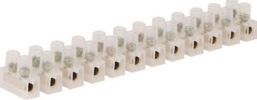
 so it seems likely EA and EB are earth, and L1 and L2 are line supplies, and one black is neutral. The earth seems likely the one wire one is sure what it is, so we can reference using that wire to start with. So step one put wires in a junction block so safe to work with this
  is cheap enough, and means you can test safely. This
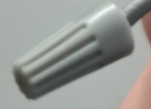
  on one black and one grey wire, so most likely is brown to L1 and black to L2 and one grey and one black into nut
  likely an error will just trip the MCB or RCD but better if that does not happen.
I assume you are refering to the other switch of the 2 way pair. A picture of the wiring there would be very helpful in our diagnosisthe 2nd switch (one I haven't touched at all)

I assume you are refering to the other switch of the 2 way pair. A picture of the wiring there would be very helpful in our diagnosis

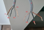
One starts by labelling so you can test and remember what you have found View attachment 347186 so it seems likely EA and EB are earth, and L1 and L2 are line supplies, and one black is neutral. The earth seems likely the one wire one is sure what it is, so we can reference using that wire to start with. So step one put wires in a junction block so safe to work with this View attachment 347187is cheap enough, and means you can test safely. This View attachment 347188 goes here View attachment 347189 and leads into View attachment 347190 so you are measuring AC volts on the 700 volt range. Set before you use, and don't turn dial after, so you are looking for 230 volts, but the exact reading does not matter, so start point is confirming the two browns are live feeds. So brown to earth shows 230 volts.
You can't test for neutral with the meter, line in to line out and line in to neutral will both show 230 volts, but the picture seems to show one grey is neutral and the other disconnected, so also likely neutral.
So it seems likely one black and one grey is line out, one could look in ceiling rose to confirm, but seems likely you want wiring nuts View attachment 347191 on one black and one grey wire, so most likely is brown to L1 and black to L2 and one grey and one black into nut View attachment 347191 likely an error will just trip the MCB or RCD but better if that does not happen.
I am dyslexic, so may be better to wait and see if anyone corrects my logic.
That makes things easier, assuming that second switch cable comes directly to the first switch and not via the light fitting or a junction box, we now believe one of the cables has no power on it, checking with the meter should soon verify this and which cable is which.Hi, at work currently but I do have a photo of the 2nd switch. The 2 way that I'm having trouble with is the switch that is 2nd from left:
View attachment 347193

Errrrrrrrrrrrr...... WHY?And surely the COM of the two-way wiring must be Brown...
pm being sentThanks for your suggested wiring / picture mate ,but I can't see how the switched live to the light fitting ( two way one) will be routed to it, as in your pic it would be the grey wire from the other cable ,which would be odd. Or am I missing something?

Brilliant, well done.Thank you everyone for the advice, especially helpful was the diagram labelling the new terminals to match the old. Also a huge thanks to terryplumb who kindly spent an hour on the phone with me troubleshooting (we've found there's something wrong with my earth wire(s) which means I still need an electrician to come over at some point). But for the time being, the new light switch is wired up and everything works perfectly!
View attachment 347249

??You have what is known as a two gang three way switch
If you need to find a tradesperson to get your job done, please try our local search below, or if you are doing it yourself you can find suppliers local to you.
Select the supplier or trade you require, enter your location to begin your search.
Are you a trade or supplier? You can create your listing free at DIYnot Local
