Octal Relay Housing

Joined
28 Jan 2011
Messages
57,313
Reaction score
4,295
Location
Buckinghamshire
Country
United Kingdom
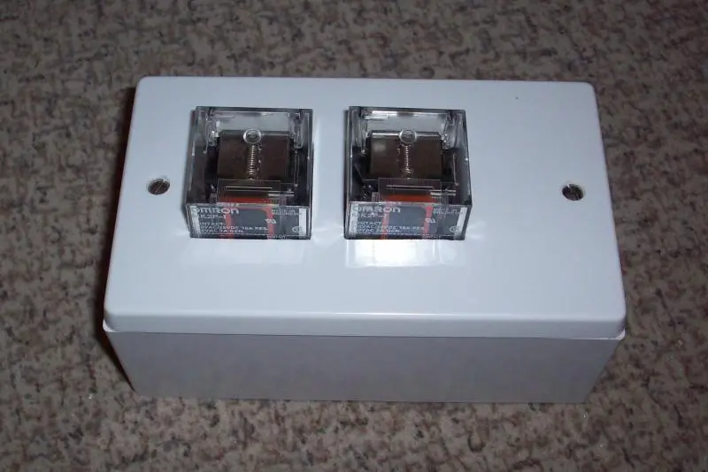
We touched on this a few months ago. I've been experimenting with various ways of housing octal plug-in relays, in situations in which I ideally don't want to have to use a large enough enclosure to totally 'enclose' them (and thereby also totally deprive them of ventillation/cooling) - so I wonder what people think about have the ends of them 'exposed'. For example, one of the experiments is:
Kind Regards, John.
 
Sponsored Links
Would it not be OK to have them completely exposed, thus avoiding the need to cut rectangular holes, which as you know is impossible to do neatly by hand?
 
Being the devils advocate here but I see a couple of problems. Some relays have buttons or sliders on the top to manually activate and also by pulling out the relay one may have access to parts which should require a tool to access.

So I would say either or!

Either have the whole relay exposed so the lid is too close to the base to not comply with the 1mm rule. Or contain them completely.

I have in the past talked about this tool rule and something as simple as a tie rap could get around the problem. If one has to cut the tie rap with side cutters you have used a tool so will comply.

The box does look neat and as a Radio Ham I would use something like that in my shack without any problems but at work there is always some daft twit would has no sense and will fiddle for the sake of fiddling.

In some where like a switch room where there is limited access then great I did not read your previous posts on this.
 
Sponsored Links
Would it not be OK to have them completely exposed ....
I'm not really sure how one could do that. With the sort of bases that are common these days, that would leave all of the terminals exposed; I haven't seen ones with shrouds. I have, in the past, used standard octal valveholders mounted on the inside of the box, with the apology for a skirt around the pins (about 0.5mm , if that, entering an oversized hole in the box, but it's then still possible to withdraw the relay to the extent that it's pins are still mating with the socket, but exposed. Did you have some other technique in mind?

thus avoiding the need to cut rectangular holes, which as you know is impossible to do neatly by hand?
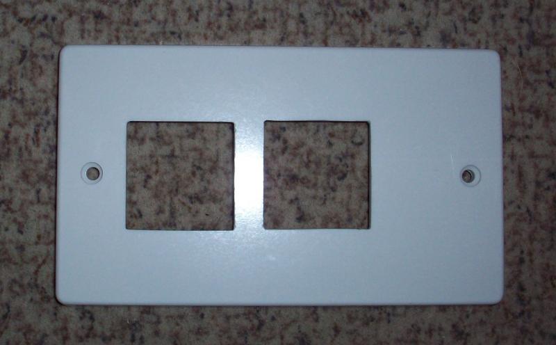
As you may be able to just about see, they're pretty neat holes (even if I say so myself) - but, as you say, they are a pain to create. What on earth is the material that these 'moulded' accessories are made out of - presumably some thermosetting plastic, a modern equivalent of bakelite? Although it's thermal properties are very good for the job, it has to be one of the least forgiving materials I have ever had to work with!

Kind Regards, John.
 
If you're going to leave them exposed you should use the bases with a sprung clip for securing the realy....
I know that's the theory, and the bases I've used do have wire retaining clips, even though fitting them (with the arrangement shown) would requiring worsening the 'IP status' of the enclosure. However, anyone who really thinks that those retaining clips are necessary has presumably never tried to pull one of those relays out of it's base - one is lucky if one manages it with destroying the base!

Kind Regards, John.
 
Being the devils advocate here but I see a couple of problems. Some relays have buttons or sliders on the top to manually activate and also by pulling out the relay one may have access to parts which should require a tool to access.
Yes, there is a theoretical problem if someone pulled out the relay. In practice, given how tight the sockets usually are, it's unlikely that anyone would be able to pull the relay out with so little exposed 'to get hold of' - but I agree that it could theoretically happen

So I would say either or! Either have the whole relay exposed so the lid is too close to the base to not comply with the 1mm rule. Or contain them completely.
I've just explained the problem with the 'either' in my response to BAS - I don't think it's safe. Complete enclosure is obvioulsy the simplest solution.

As for 'the 1mm rule', it would be the front face we're talking about (when box mounted on wall) so, per BS7671, it would actually be a '12mm rule' (IP2X/IPXXB).

I have in the past talked about this tool rule and something as simple as a tie rap could get around the problem. If one has to cut the tie rap with side cutters you have used a tool so will comply.
Yes, I've used variations on that theme in my time.

Kind Regards, John.
 
I'm not really sure how one could do that. With the sort of bases that are common these days, that would leave all of the terminals exposed;
For example:

ACS-8_zm.jpg


but it's then still possible to withdraw the relay to the extent that it's pins are still mating with the socket, but exposed.
Does not appear to be an issue with some very expensive electrical equipment, usually installed on open shelves in people's living rooms at an easily accessible height, where the pins exposed are carrying voltages considerably higher than 230.


As you may be able to just about see, they're pretty neat holes (even if I say so myself) - but, as you say, they are a pain to create.
Pretty neat, yes.

Round would be easier and neater. Do it in metal and you can use a chassis punch.


What on earth is the material that these 'moulded' accessories are made out of - presumably some thermosetting plastic, a modern equivalent of bakelite? Although it's thermal properties are very good for the job, it has to be one of the least forgiving materials I have ever had to work with!
Some kind of polycarbonate, I think. Brittle. Does have the advantage of being rigid though - ABS would be easier to work, but that flexes.

If you want rectangular and neat you could try clamping thin strips of metal across the face to act as stops for your file.

Metal enclosures, chassis punch, bases like the one above - you know it makes sense.
 
I doubt that totally enclosing them in a large metal enclosure will cause issues with heat, if so then it is possible to get vents.
Any reason for using octal relays over contactors etc?
 
As you may be able to just about see, they're pretty neat holes (even if I say so myself) -
Kind Regards, John.

I agree, bit off centre :D but neat.
Some makes do pvc blanks which are easier to cut
 
Put them fully inside a box. They don't need to be ventilated.

Or, just buy smaller relays.
 
I agree, bit off centre :D but neat.
I'm glad you agree - not perfect, but there was a limit to how much time of was prepared to waste just for an 'experiment' which was probably never going to be used in anger:
It is a trecherous material, and what you see was essentially the result of 'dentistry' - a dental diamond burr in a very high speed mini-tool then just tidied by hand/eye with a file.

Off-centre, of course, to leave room for a connector block to the right :)

Some makes do pvc blanks which are easier to cut
I've looked, but failed to find such animals. There are plenty of PVC ('conduit') boxes around, but none I've seen have offered PVC blank plates. I have, however, been known to use sheets of more user friendly materials for such purposes!

Kind Regards, John.
 
Put them fully inside a box. They don't need to be ventilated.
That's generally what I've been doing so far - but was exploring some alternatives (with the predicted reactions!)

Or, just buy smaller relays.
Yep, another good option, but I've got an awful lot of those animals - and, if I ever run out, replacements will probably be available 'for ever'!

Kind Regards, John
 
I doubt that totally enclosing them in a large metal enclosure will cause issues with heat, if so then it is possible to get vents.
Agreed
Any reason for using octal relays over contactors etc?
A mixture of history, cost, size and availability (at sensible cost). I have a lot of these things around my house, and many are due for 're-housing' (or replacement). They have a mixture of 230V AC and 12V DC coils, and none are switching appreciable loads. If I could find 'single module' 2-pole contactors (not difficult) with both 230V AC and 12V DC coils (seemingly next-to-impossible) at sensible prices in comparison with octal relays (very unlikely), then I'm sure I'd replace them all with contactors in DIN enclosures.

Kind Regards, John.
 

DIYnot Local

Staff member

If you need to find a tradesperson to get your job done, please try our local search below, or if you are doing it yourself you can find suppliers local to you.

Select the supplier or trade you require, enter your location to begin your search.


Are you a trade or supplier? You can create your listing free at DIYnot Local

 
Sponsored Links
Back
Top