PT100 Sensor Wiring

Please can someone help me again?

I have wired up the above circuit, but it isn't working.

The display shows 300 all the time. At first I thought the transmitter may be faulty, but I bought some resistors and wired it in like below, as far as I am aware, this should show around 120 (ish) on the display.
But the display still shows 300, which has got me thinking that the transmitter may be ok, and it is actually the diplay at fault? The display was programmed before it left the shop to display between 0-300 on 4-20mA.
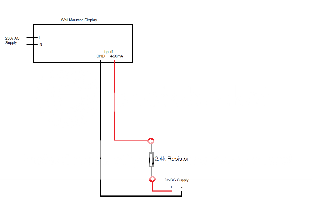
Display3.png


I have checked the the input is correct on the display, and all switches are set correctly etc.


Anyone have any idea what I could try next please?


Thanks a lot
 
Sponsored Links
It might be that the display sources the voltage for the 4-20 mA loop. If it is and the voltage is around 24 then the total voltage in the loop is 48 which across the 2.4 k ohm resistor will be 20 mA giving full scale 300.

Disconnect the loop from the display and with the mains on measure the voltage across the 4-20 mA input terminals of the display. It should be very close to zero, if there is a voltage then the display is sourcing power for the loop. This is quite normal as it removes the need to have power at the sensor other than power from the 4-20 mA loop.

Or connect the 2.4 kohm resistor across the input terminals with out the external power supply,
 
Thanks for the replies. I will try what you suggested today.

The make of the display is a KIMO ATT300.


Thanks a lot
Ryan
 
Sponsored Links
Hi,

Yes I double checked that switch f is in the correct position, and I am using Input 1, as I was told by the company which I bought it off this is the input which he programmed for me to use.


Thanks a lot
 
Only other thing to check is measure the input current from the loop with a multimeter, you'll need one with a range that measures milliamps DC such as a fluke 77 or similar.
 
Switch d was in the correct position :)


I've returned the display to the supplier now! As I'm sure it should have worked the way I wired it up.
 
Certainly would have thought so.

Would be worthwhile checking that you have a mA current loop through that transmitter in the meantime.
Have you got a multimeter capable of measuring mA ?
or volts ?
If so, wire the transmitter up again with the power supply but instead of the wires going "into" input 1 of the indicator put them onto the tails of, say a 250ohm resistor.
Put your meter in series in the current loop.
Measure the 4-20mA current, this will confirm the transmitter is working.
Heat up the temperature probe and the current should change.

You can also measure the volt drop across the resistor, in this case 1-5volts.

This is also working towards the next step in checking the display, a couple of wires from each end of the resistor into the voltage input terminals of the indicator. (bit late now though, but once you get it back you can give it a go).
 

DIYnot Local

Staff member

If you need to find a tradesperson to get your job done, please try our local search below, or if you are doing it yourself you can find suppliers local to you.

Select the supplier or trade you require, enter your location to begin your search.


Are you a trade or supplier? You can create your listing free at DIYnot Local

 
Sponsored Links
Back
Top