Replacing Drayton and British Gas Timer with Google Nest

Joined
15 Nov 2024
Messages
4
Reaction score
0
Country
United Kingdom
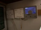
I have a Drayton Digistat wireless(thermostat, I think) and British Gas timer and I want to replace it with Google Nest.

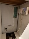
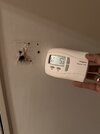
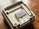
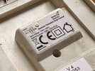
The receiver was sitting on the wall and I removed it. It is wireless but I saw a hole in the wall behind it (new house) which is ideal so I can feed USB power to Nest Thermostat.

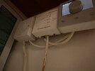
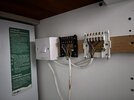
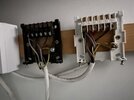
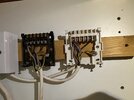
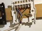
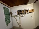
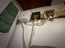
Now to install the heat link, would I need to access the boiler at all seeing as all the cabling has been done already? Have a look at the low angle pictures of the receiver and timer to show where and how the cables are patched. Hopefully this gives you an idea.

The boiler is a Vaillant Boiler.

Any suggestions or step but step would be incredibly appreciated.

I tried searching the web but couldn't find anything about how to replace nest with these two.

I am not a qualified electrician but very handy with things and a safe pair of hands.

Thank you
 

Attachments

  • IMG_8698.jpeg
    IMG_8698.jpeg
    137.5 KB · Views: 20
  • IMG_8699.jpeg
    IMG_8699.jpeg
    94.7 KB · Views: 22
  • IMG_8700.jpeg
    IMG_8700.jpeg
    136.5 KB · Views: 17
  • IMG_8701.jpeg
    IMG_8701.jpeg
    139.7 KB · Views: 20
Sponsored Links
have a Drayton Digistat wireless(thermostat, I think) and British Gas timer and I want to replace it with Google Nest.
With the power turned off from the FCU switch, could you show us the wiring behind the digistat receiver and BG programmer?
 
I took the covers off and took pictures.

The black one is Digitstat and White one is BG Programmer.
 

Attachments

  • IMG_8703 3.jpeg
    IMG_8703 3.jpeg
    234.8 KB · Views: 19
  • IMG_8704 3.jpeg
    IMG_8704 3.jpeg
    251.6 KB · Views: 20
  • IMG_8705 3.jpeg
    IMG_8705 3.jpeg
    211.4 KB · Views: 21
  • IMG_8706 3.jpeg
    IMG_8706 3.jpeg
    273.6 KB · Views: 21
  • IMG_8707 3.jpeg
    IMG_8707 3.jpeg
    295.9 KB · Views: 15
  • IMG_8708 3.jpeg
    IMG_8708 3.jpeg
    207.6 KB · Views: 18
  • IMG_8709 3.jpeg
    IMG_8709 3.jpeg
    197.4 KB · Views: 20
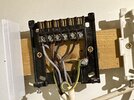
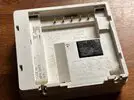
If it helps, here's the back of Digistat control panel i took off
 

Attachments

  • IMG_8710.jpeg
    IMG_8710.jpeg
    278.4 KB · Views: 5
Sponsored Links
And here's the back of BP Programmer panel I took off
 

Attachments

  • IMG_8711.jpeg
    IMG_8711.jpeg
    282 KB · Views: 5
  • IMG_8712.jpeg
    IMG_8712.jpeg
    217 KB · Views: 5
I am not sure how wired, the normal method with a modern boiler is the supply to the thermostat/timer/hub comes from the boiler, so it can't in error by-pass the boilers fuse, but with earlier boilers the whole boiler was simply turned on/off, in fact this is how my boiler works.

So can work out enough to make it work, but to work out have to make it work safely, so no fuses are by-passed can't do from pictures shown.

We are told all should be powered from the same 230 volt supply, or use batteries, two reasons, one is again so no protective device is by-passed, but the other is to ensure any uninterruptible supply (UPS) feeds all needed for the central heating to run, so the supply to the USB power supply should come from the boiler supply.

I have also fitted Nest Gen 3, as it means two wires from the heat link to the thermostat allow supply to thermostat, CH control and DHW control all with just 2 wires, however since fitting, been rather disappointed with it, and have fitted Wiser as well, as the Nest will not link to TRV heads.

So I have labelled the cables 1 and 2.
1731761587790.png

cable 1 is the live feed, Brown is Line, can't quite make out colour of the neutral but with Nest Gen 3 that cable goes to L and N
1731761824191.png
wire 2 grey is neutral (N) and brown is line (L) and the black seems to be switched line, so will go to 3 on Nest Gen 3 with a link from L to 2 (common). I am assuming not domestic hot water? There is a terminal for the earth, may as well use it.

I found very limited space in the Nest Gen 3 heat link, so mounted a junction box below it, but you have less wires to me.

I was very disappointed with Nest Gen 3, had to disable most of the features, geofencing caused a very cold house when EE mast went down, the anti legionnaires function was firing up boiler when not required, it is still connected but only really to work DHW if we have poor solar days in the summer.
 
It appears that you have a white, flat, twin and earth cable feeding the boiler FCU (fused connection unit). The cables are then daisy chained through the BG Programmer and Drayton SCR.

So, to summarise; Eric's comments above related to system components being fed from the same circuit, are largely irrelevant - the boiler and controls do appear to be fed from the same FCU.

So I have labelled the cables 1 and 2.
cable 1 is the live feed, Brown is Line, can't quite make out colour of the neutral but with Nest Gen 3 that cable goes to L and N wire 2 grey is neutral (N) and brown is line (L) and the black seems to be switched line, so will go to 3 on Nest Gen 3 with a link from L to 2 (common).
This is mostly correct, but to state in a clearer way, and to aid with wiring up the Heatlinks small terminals...

With cable one, connect:
Brown wire, to Nest Heatlink L
Blue wire, to N
Green/Yellow wire, to the earth terminal

With cable two, connect:
Brown wire to Nest Heatlink terminal 2
Grey wire to N
Black wire to terminal 3
Add a short link wire between Heatlink terminals L and 2
Green/Yellow wire, to the earth terminal

There is a terminal for the earth, may as well use it.
Just to add, because these cables are daisy chained, the green/yellow wires MUST remain joined to each other.
Connecting them together within the Heatlinks earth terminal, will retain earth continuity to the boiler.
 

DIYnot Local

Staff member

If you need to find a tradesperson to get your job done, please try our local search below, or if you are doing it yourself you can find suppliers local to you.

Select the supplier or trade you require, enter your location to begin your search.


Are you a trade or supplier? You can create your listing free at DIYnot Local

 
Back
Top