Replacing ESI ESRTP6C with Nest Thermostat (3rd Gen) - Dual Zone

@RandomGrinch thank you very much for your extensive advice on this thread. I also mustered up the courage to swap out my ESI thermostats (same models and wiring centre as OP) for Tado thermostats.
That's quite alright :)
Good for you, for having a go.

Whilst the thermostats do successfully fire the system up, I do get random “calls for heating” on the boiler at times and I wonder if that’s because of additional circuitry in the ESI thermostat units (resistors or diodes?).
Although there are extra components, there is nothing 'smart' going on with the circuitry - there are no ICs for example.
Theoretically, there is no real difference to the circuit having the Tado, or the original ESI thermostats connected.

You could try disconnecting the +5V to the Tado and see if that helps, but the issue may be elsewhere.

Do you have a boiler that has a pre-heat function for example?
 
Sponsored Links
Thanks for the followup @RandomGrinch, I decided to temporarily re-connect the ESI thermostats in place of the Tado units. I'm waiting to see if I can catch the boiler starting up with a call for heat when it shouldn't.

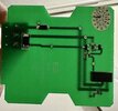
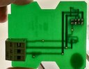
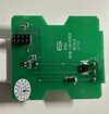
Before I did re-connect the ESI thermostats I decided to take apart the backplate PCB to examine its PCB closer (the thermostat plugs onto this base plate). There does seem to be a few components, I attached a few photos and labelled the components.

Agreed, there doesn't seem to be anything smart, just wondering if there's some passive components that stop RH floating.
 

Attachments

  • IMG_1914.jpeg
    IMG_1914.jpeg
    201.2 KB · Views: 76
  • IMG_1915.jpeg
    IMG_1915.jpeg
    187.5 KB · Views: 77
  • IMG_1916.jpeg
    IMG_1916.jpeg
    210.2 KB · Views: 98
Wow, you have certainly fully evaluated my system.

What would be the benefit from attempting to remove 2 valve PSU from the system entirely?

FYI - The sytem has been working 1.5 days and I've had no issues with it.

I'm not sure what "issues" I would have or should be looking out for the boiler kicks in and turns off according to the temp on the two stats.
Has this still been working ok for you? I very tentative tried a similar way of wiring myself. But measured a pull up resistor inside of the room stat which put me off. Concerned that the dry contact, straight pass through of the nest controller might cause issues.
 
I have just read most of the thread, and the question in my mind is why? Nest is such a poor system to start with, it simply is not designed for use with linked TRV's, the geofencing is rotten, can't set distance, and when placed in learning mode it is like a mischievous little boy.

My boiler does not modulate, so a little to gas boilers, but with a gas boiler which modulates you need to allow it to do its stuff, and not by-pass the built in controls. In the main gas boilers are analogue, so the controls also need to be analogue, be it a TRV slowly opening or closing, or a 0 - 40 volt signal, the only on/off controls are for when the boiler is no longer required, often using geofencing.

The problem is not all boilers are designed to use electrical controls, some are designed to use the temperature of the return water, so the controls in the main depend on the boiler.

It does seem people can't read, the government has said heating systems must be able to select rooms or groups of rooms when the home exceeds a set size, and the TRV does this, however it seems some have read into the rules that it must have motorised valves, well using electronic TRV's they are motorised valves.

But the problem is getting things to integrate, I looked at my mothers Bosch boiler, and although it modulated, there was no option for electrical control of the modulation, it did not even tell you how much it had modulated, it seemed every time it was electrically switched off, and back on again, it restarted flat out, but if it was allowed to turn off due to return water temperature, then it switched on again fully modulated.

So the clever thermostat fitted,
84067_P.jpg
was designed to adjust the mark/space ratio as approaching the target temperature, this would have worked very well with my oil boiler, but was not suitable for the gas boiler it was fitted to as it defeated the built in modulating software.

But the problem was it worked, may be not in an efficient manor, but since it worked, it was hard to convince anyone it was wrong, I did fit electronic TRV's which took some setting up of the lock shield valves so they did not over shoot, but once set up it worked well, and gas use went down, the TRV's were claimed to work with Nest, but they didn't.
 
Sponsored Links
I have just read most of the thread, and the question in my mind is why? Nest is such a poor system to start with, it simply is not designed for use with linked TRV's, the geofencing is rotten, can't set distance, and when placed in learning mode it is like a mischievous little boy.

My boiler does not modulate, so a little to gas boilers, but with a gas boiler which modulates you need to allow it to do its stuff, and not by-pass the built in controls. In the main gas boilers are analogue, so the controls also need to be analogue, be it a TRV slowly opening or closing, or a 0 - 40 volt signal, the only on/off controls are for when the boiler is no longer required, often using geofencing.

The problem is not all boilers are designed to use electrical controls, some are designed to use the temperature of the return water, so the controls in the main depend on the boiler.

It does seem people can't read, the government has said heating systems must be able to select rooms or groups of rooms when the home exceeds a set size, and the TRV does this, however it seems some have read into the rules that it must have motorised valves, well using electronic TRV's they are motorised valves.

But the problem is getting things to integrate, I looked at my mothers Bosch boiler, and although it modulated, there was no option for electrical control of the modulation, it did not even tell you how much it had modulated, it seemed every time it was electrically switched off, and back on again, it restarted flat out, but if it was allowed to turn off due to return water temperature, then it switched on again fully modulated.

So the clever thermostat fitted, View attachment 304576was designed to adjust the mark/space ratio as approaching the target temperature, this would have worked very well with my oil boiler, but was not suitable for the gas boiler it was fitted to as it defeated the built in modulating software.

But the problem was it worked, may be not in an efficient manor, but since it worked, it was hard to convince anyone it was wrong, I did fit electronic TRV's which took some setting up of the lock shield valves so they did not over shoot, but once set up it worked well, and gas use went down, the TRV's were claimed to work with Nest, but they didn't.
None of this adds any value to the original thread, nobody needs to justify to you why they want a particular thermostat.
 
But measured a pull up resistor inside of the room stat which put me off. Concerned that the dry contact, straight pass through of the nest controller might cause issues.
It's easy for me to say, as I don't have the system, but I'm confident there shouldn't be any concerns.
Having another quick look at the circuit diagram - post #12, the inputs to the controller go directly to a standard 5V DC coil relay.
On the PCB, there is a diode to protect against reverse EMF, but what I thought was a pull-up resistor, now looks like more reverse EMF protection. I.e. a pulse generated by the coil is then absorbed by the capacitor/resistor pairing.

So, no matter what pull-up resistors may be in the thermostat, all that we are dealing with on the controller, is a standard relay. Using a Nest ( or whatever) to connect 0V to RH should operate that relay.

Otherwise, you could consider rewiring the connectors on the zone valves for direct 230V operation.
 
Agreed, there doesn't seem to be anything smart, just wondering if there's some passive components that stop RH floating.
Thanks for the PCB pic, I'm afraid I haven't looked into it properly yet.

The reason why I suggested the wiring to the Nest with RH on common, was to supply +5V to the relay when the heating was supposed to be off. RH would definitely not float, and with +5V on both sides of the coil, the relay should be off.
That's why it was a bit odd that you seemed to have problems.
As I said above, this is a standard relay - it isnt exactly a super sensitive electronic device! :)

The other thing that may be worth considering, when Nest is new, it goes through a learning phase; it may be possible that spurious calls to heat could occur?

EDIT - sorry, yours is the Tado - I don't know if there is a learning phase for that. It may be worth investigating though?
 
Last edited:
Hi all,
Very useful thread. I too have just moved in to a new build with one of these PCB board.
I think ive understood what @Chigurh did to get it working.

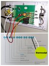
Just want to confirm that the end result was something like this.
 

Attachments

  • signal-2023-11-15-17-09-01-703.jpg
    signal-2023-11-15-17-09-01-703.jpg
    167.4 KB · Views: 357
Just want to confirm that the end result was something like this.
Nearly, but not quite - with potentially damaging consequences to the PCB! :eek:

DO NOT add a link between Live and terminal 2 on the Heatlink - that would create a direct connection between live and the (extra) low voltage side of the ESI PCB - big bang likely!

Additionally, if you are using connectors T1 and T2 to power the Nest thermostat, the earth terminal on the Heatlink should also be connected.

image32.png


If there are any problems, try removing the brown wire between +5V and terminal 1 on the Heatlink; this wire may not be strictly necessary.
 
Just for fun, very simple really - it wouldn't be too complicated to remove the 2 valve PSU from the system entirely...

View attachment 294849
Some guesswork was involved - double check before modifying your own system! ;)
Doh! Just realised, after all this time - the colours of pins 1 and 2, on the zone Valve connectors (in my schematic) are transposed :rolleyes:

Pin 1 would be the blue wire to the synchro motor, pin 2 would be the brown wire.
 
@RandomGrinch @comet2174946184
Thankyou both for fleshing this out. I had given up trying to change the thermostats on my exact same ESI system. I had an attempt last year with Tado but sent them back.
I was about to press the button on paying for Hive with professional fitting until I came across your thread.
Instead I bought Hive components stand alone from screwfix saving some £200. Fitted them at the weekend and BOOM works perfectly.
Thankyou both very much
 
Sorry, late post but do you have a final picture as I'm struggling to find the correct way with the exact same esi pcb
 

DIYnot Local

Staff member

If you need to find a tradesperson to get your job done, please try our local search below, or if you are doing it yourself you can find suppliers local to you.

Select the supplier or trade you require, enter your location to begin your search.


Are you a trade or supplier? You can create your listing free at DIYnot Local

 
Sponsored Links
Back
Top