Resistor hot in bathroom extract

From memory, my fan uses a capacitor dropper, and so generates much less waste heat.
At first sight, one would think that would be preferable, although I've taken apart a good few timer modules over the years, and have never found anything other than a resistor.

I'm quite a fan of capacitive droppers, and use them fairly extensively in my house for 'switched dimming' of lights (my experience with 'actual dimmers' and LEDs not being very happy ones!) - and for predominantly 'resistive' loads, that works fine.

So why don't they (at least, usually) take that approach in these timer modules? Looking at the circuits I posted give one immediate thought. What would be the dropper 'capacitor' would be in series with a 'big fat electrolytic capacitor' (and the rectifier diode) across the supply. That means that, at 'switch on' there could be an initial very brief period of very high current - only for a few milliseconds, but perhaps for long enough to kill the rectifier diode ??

Kind Regards, John
 
Sponsored Links
Thanks John, this is very helpful. ... And yes, I was referring to the diagnosed autopsies that you put together, sorry for the confusion.
The house had a dimmer fitted to the bathroom when I bought it, and the fan worked for several years (and I think the fan has been there since new, so now getting towards 25 years old), but the timer started misbehaving a couple of years ago.
You're welcome. As I said, although I've never personally tried it, I would be fairly surprised if a dimmed supply to the light wouldn't trigger the timer module successfully (provided, perhaps, the light wasn't dimmed to a 'ridiculous extent') - but it is for you to find out if I'm right ;)

Kind Regards, John
 
As I've said, if one half-wave-rectifies a sine wave supply, the RMS of the rectified voltage will be the original RMS divided by √2, not (as you seem to have assumed) divided by 2
Someone has asked me, off list, to explain the reason for the above - so, in case anyone else doesn't know, but would like to ...

"RMS" voltage is shorthand for "Root Mean Square" voltage - and that means the square root of the "mean square voltage", that being the average (arithmetic mean) of the squares of the instantaneous voltage at every point in time during a cycle (or any whole number of cycles) of the AC waveform. That is true for any waveform.

In essence, the explanation of the above is simply this - when one half-wave rectifies (i.e. only every other half cycle present, the voltage being zero during the other half-cycle), "the instantaneous voltage at every point in time" during one of the half-cycles (hence also the square of that voltage) during one of the half-cycles reduces to zero, so the average of those squared voltages (the mean square) reduces by a factor of 2 (i.e. halves). However, when one takes the square root of that to get RMS, then the reduction (compared with the situation without rectification becomes a factor of 'the square root of 2'.

It sounds complicated, and may be difficult to understand when written in prose as above. If anyone has difficulty, I can try a different way of explaining, based on 'areas under the curve' of a plot of the 'voltage squared'.

Some simple relationships follow from the above, with examples of a 240V RMS supply:

...With an RMS of 240V, the peak voltage is 240 x √2 = about 340V. That remains true after half-wave rectification.
...With half-wave rectification of a 240V RMS supply, the RMS reduces to 240 / √2 = about 170V
...It follows from the above two relationships that with half-wave rectification of any supply voltage, the RMS of the half-wave rectified voltage is half the peak voltage - so, again, if the peak voltage is about 340V (both rectified and unrectified), then with half-wave rectification, the RMS becomes 340 / 2 = 170V

I hope that may possibly afford a little help to at least some people!

Kind Regards, John
 
As I have explained in my earlier posts, your approach/calculation appears to be flawed.

You have effectively assumed that the RMS voltage of a half-wave-rectified sine wave is a half of the RMS voltage of the full waveform before rectification, which is not correct. ....

As I've said, if one half-wave-rectifies a sine wave supply, the RMS of the rectified voltage will be the original RMS divided by √2, not (as you seem to have assumed) divided by 2 - i.e. (forgetting the 15V offset, for convenience) about 170V (rather than 120V) in the case of a 240V supply. ... and, of course, it's that RMS figure which determines how much power will be dissipated in the resistor.

Kind Regards, John
Thank you for your "input" to this discussion and your correction to my assumptions/calculations.

At the time when I submitted these calculations there was (in the back of my mind) that something may have been incorrect in my "logic" in determining the RMS value of a "half-wave" rectification.

You are correct and I have verified this on various "references",
including "https://www.redcrab-software.com/en/Calculator/Electrics/Sinus-Pulse-RMS-One-Way "

Hence, the resistor concerned would be dissipating about 1.32 W, as you calculated.

It "may be" that the designers of this device also did not fully understand the mathematical; calculations involved in determining this "dissipation" and made the same assumption/error - as did I.

Since it has now been "proved" that the resistor concerned is dissipating about 33% above its capacity, it would be a good idea of the OP were to
replace this 1 W, 22 kΩ with two 1 W, 11 kΩ resisters in series
(or one 1 W, 10 kΩ resistor in series with a 1 W, 12 kΩ resistor),
if there is space so to do in the place where the "board" and the existing resistor is located.
Such a vertical arrangement of series resistors would give more "air flow" around them - away from the "board".
 
Sponsored Links
I'm still trying to see any evidence for the resistor being 1W. It could just as easily be 2W in that form factor, and note that it is not the resistor that discoloured, but the pcb.
 
Could be a 3 watt wire wound ceramic resistor

watt1-10 size.jpg
 
Could be a 3 watt wire wound ceramic resistor

View attachment 311179
Would be good to know as after I replace the capacitor, could be the next part destroyed (by it's own) heat. At the moment trying to find a place that sells Kapton/Polyimide tape for a reasonable price that is not the "fake" stuff from Amazon/Ebay.
 
Forget the tape - it won't have any useful effect. The resistor must be at least 2W as it is dissipating more than a Watt. The weak point is the PCB which cannot stand continuous temperatures of that kind, so at least space the resistor off the PCB using ceramic beads.
 
Any ideas what temperature this resistor could be possibly be getting up to?
 
Thank you for your "input" to this discussion and your correction to my assumptions/calculations.
You're welcome.
You are correct and I have verified this on various "references", including "https://www.redcrab-software.com/en/Calculator/Electrics/Sinus-Pulse-RMS-One-Way "
Hence, the resistor concerned would be dissipating about 1.32 W, as you calculated.
I'm glad that you and your calculators agree my my calculation :)
It "may be" that the designers of this device also did not fully understand the mathematical; calculations involved in determining this "dissipation" and made the same assumption/error - as did I.
Possibly. However, I would suspect that it's more likely that the assumption that it is a 1W resistor (and assumption made only by you) is incorrect.

Kind Regards, John
 
I'm still trying to see any evidence for the resistor being 1W. It could just as easily be 2W in that form factor, and note that it is not the resistor that discoloured, but the pcb.
There is no evidence - it's an assumption made only by FrodoOne. As has been said, it might well be a 2W or 3W wire-wound resistor (and I suspect it probably is)

However, that only makes a difference up to a point. Whilst the temp of a higher-rated resistor would not get quite so hot, it doesn't alter the fact that about 1.3W worth of heat is being generated continuously in a pretty confined space.

Kind Regards, John
 
Any ideas what temperature this resistor could be possibly be getting up to?
In my experience, far too hot to touch - so I would suspect 100°C or higher (up to about 60°C is just about 'touchable').

Someone might know what temp it takes to scorch a PCB (since that scorching is often very pronounced)

Kind Regards, John
 
What might sound daft as underspec by a manufacturer does happen sometimes. Back in the late 70s/early 80s an ex-co-director of a small company manufacturing company told me of his old company omitting something as simple as a reverse voltage protection diode to the control panels to save money. Now bearing in mind that I as a private person could by that as a single diode for about 7p it sounded nonsensical in the extreme compared to the circuit damage risk. However, since they were making thousands of these units at a time then this item and others were collectively saving the company a few quid
 
There is no evidence - it's an assumption made only by FrodoOne. As has been said, it might well be a 2W or 3W wire-wound resistor (and I suspect it probably is)

However, that only makes a difference up to a point. Whilst the temp of a higher-rated resistor would not get quite so hot, it doesn't alter the fact that about 1.3W worth of heat is being generated continuously in a pretty confined space.

Kind Regards, John
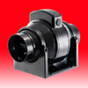
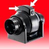
Agree the space the electrics are housed in is confined and unvented, see image below. There is probably no ventilation holes given it is primarily a bathroom extractor and Manrose needed to maintain the IP rating. However, the fan sits in line (in the loft) away from the moisture of the bathroom and the electrics in the separate space from the ducted air. I am now tempted to drill some fine vent holes in the electrical casing so heat can escape. Either on the top or at the sides. I can add a shroud also so let's say by some extreme bad luck the roof leaks right above the fan, the water still has no way to ingress the small holes I have drilled.
 

Attachments

  • MRMF100T.jpeg
    MRMF100T.jpeg
    30.6 KB · Views: 50
  • MRMF100T.jpeg
    MRMF100T.jpeg
    57.3 KB · Views: 53
What might sound daft as underspec by a manufacturer does happen sometimes. Back in the late 70s/early 80s an ex-co-director of a small company manufacturing company told me of his old company omitting something as simple as a reverse voltage protection diode to the control panels to save money. Now bearing in mind that I as a private person could by that as a single diode for about 7p it sounded nonsensical in the extreme compared to the circuit damage risk. However, since they were making thousands of these units at a time then this item and others were collectively saving the company a few quid
Indeed - and if one wants to be cynical, it can sometimes be far 'worse' than just the saving of a few quid in manufacturing costs.

The concept of deliberately "built-in obsolescence' (or 'risk of premature failure', in a case like you describe) is far from unknown - perhaps most dramatically seen in relation to car body metalwork, given that cars were generally 'rotting to pieces within a decade or so, long after the time when manufacturers knew how the situation could be dramatically improved!

Kind Regards, John
 

DIYnot Local

Staff member

If you need to find a tradesperson to get your job done, please try our local search below, or if you are doing it yourself you can find suppliers local to you.

Select the supplier or trade you require, enter your location to begin your search.


Are you a trade or supplier? You can create your listing free at DIYnot Local

 
Sponsored Links
Back
Top