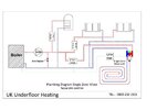
S plan pipework plan

Joined
27 Dec 2006
Messages
671
Reaction score
13
Location
London
Country
United Kingdom
This diagram is pretty much my system plan, albiet with two ufh manifolds....

Can anyone advise as to where expansion vessel should sit? Filling loop? Preassure guage (or guages?)
And, should I fit automatic air venting valves? If so, where?

Many thanks for any input...
 

Attachments

  • Plumbing-diagram-Single-zone-mixer-separate-control-e1510651554624 (1).jpg
    Plumbing-diagram-Single-zone-mixer-separate-control-e1510651554624 (1).jpg
    83.5 KB · Views: 58
Sponsored Links
if you lookup in the boiler instructions it will say if suitable for a sealed system and show recommend install position for ex vessel etc
 
Sponsored Links
With a normal sealed CH system set out - all that would live in the airing cupboard where the HW cylinder lives. Usually the filling loop, expansion vessel(EV) and gauge are all on the one manifold that the EV fits into. AAV would be on the high feed into the cylinder to vent the coil. The rads would be vented themselves. Not sure if that would be any different on an oil fired system or not.

UFH is slightly different and will usually be filled and bled at it's own manifold.
 

DIYnot Local

Staff member

If you need to find a tradesperson to get your job done, please try our local search below, or if you are doing it yourself you can find suppliers local to you.

Select the supplier or trade you require, enter your location to begin your search.


Are you a trade or supplier? You can create your listing free at DIYnot Local

 
Back
Top