Schematic of my ring main so far...

Joined
10 Jan 2013
Messages
379
Reaction score
5
Country
United Kingdom
Hi. I have mapped out some of my house's electrics and the more I probe the more questions are raised! I currently have some apparent spurs that power nothing I can find, and one spur-fed socket with no apparent source (must be a hidden junction box somewhere?)

Here is a large diagram showing you my findings so far.
Spatial relationships are approximately true to life, which gives us some clues as to where cables might go. The central square represents upstairs features, and outside of that is downstairs. Most of the cables are under the floor of the upstairs bedrooms. All sockets shown are definitely on the same circuit and they are all behind one single "fuse" on my old CU. The only other circuits are lighting (whole house) and the shower.

http://i.imgur.com/auz1BxD.png

Does anyone have any comments or suggestions? In the first instance, I want to clarify the situation of "Upstairs Socket 1" so that I can extend the ring around that point, to add more sockets to the bedroom it's in.

Thanks,
 
Sponsored Links
Test your ring main properly and you will get a better idea of a central location/socket. You can sub divide from there and work out which cable feeds what.
 
Test your ring main properly and you will get a better idea of a central location/socket. You can sub divide from there and work out which cable feeds what.

OK, I'll look into how to do that.

But without taking all the floorboards up I'm presumably going to miss things - like those junction boxes already depicted, I only found those by chance, and would have otherwise remained blissfully ignorant of the cable that apparently goes to nowhere.

And, similarly, how will I find the origin of that downstairs spur without physically tracing the cable? It's clearly not any socket or other joint that I can currently see or touch :/
 
Sponsored Links
Ideally you will need some electrical test equipment to confirm the ring final circuit and any spurs.
If you are extending the circuit, you are going to need to do testing before you commission and energise anyway.
It surprising what you might find, once you start to do some simple investigating and testing.
You have shown two downstairs sockets, indicating only one cable and you have power to the boiler, any outside lights or external power? All potential spurs from the ring final circuit.
It could also be that you have spurs from spurs or even bridged circuits, it could even be possible that it is not a ring final circuit, could be two radials connected at the same fuse, so never take things for granted.
Proper investigation and testing is required to determine what you have and then you can design any alteration from there.
Please note any additional cable buried within wall less than 50mm in depth, that is not mechanically protected will require 30mA RCD protection and additional sockets will require 30mA RCD protection regardless of this.
So if you don't currently have existing RCD protection on this circuit, that needs to be factored in.
 
Ideally you will need some electrical test equipment to confirm the ring final circuit and any spurs.

I have access to a device we use for PAT testing, is that any use?
If you are extending the circuit, you are going to need to do testing before you commission and energise anyway.
It surprising what you might find, once you start to do some simple investigating and testing.

Yes, it's already been quite surprising!

You have shown two downstairs sockets, indicating only one cable

One of those is accounted for (a spur from Upstairs Socket 1) and the other is unaccounted for. It was still live when I disconnected the "third cables" (i.e. not the two making up the presumed ring) from Upstairs Socket 2 and the junction box near Upstairs Socket 1.

and you have power to the boiler

With two cables going two and from it, though - one would assume at this stage that it's not on a spur, right?

any outside lights or external power?

One outside light, on the lighting circuit. No outside power.

It could also be that you have spurs from spurs or even bridged circuits, it could even be possible that it is not a ring final circuit, could be two radials connected at the same fuse, so never take things for granted.
Proper investigation and testing is required to determine what you have and then you can design any alteration from there.
Please note any additional cable buried within wall less than 50mm in depth, that is not mechanically protected will require 30mA RCD protection and additional sockets will require 30mA RCD protection regardless of this.
So if you don't currently have existing RCD protection on this circuit, that needs to be factored in.

Cable will go under floorboards, exclusively - thankfully I don't need to chase any into walls.

How do I find out if I have 30mA RCD protection? I've never seen that mentioned in any "add new plug sockets" guides.
 
I have access to a device we use for PAT testing, is that any use?
http://www.tlc-direct.co.uk/Book/8.1.1.htm


With two cables going two and from it, though - one would assume at this stage that it's not on a spur, right?
Never assume.


Cable will go under floorboards, exclusively - thankfully I don't need to chase any into walls.
So will your new sockets be installed in the floor, not on the walls? Or do you plan to have the cables running on the surface of the walls?


How do I find out if I have 30mA RCD protection?
Look to see if you have a RCD or RCBOs in your CU.


I've never seen that mentioned in any "add new plug sockets" guides.
Then you must be reading some seriously out of date ones - it's been a requirement for 4-5 years.


//www.diynot.com/wiki/electrics:other:books

 
I have access to a device we use for PAT testing, is that any use?
No, to do the tests correctly and confirm safe installation you will require to do, for fault finding and under minor works (this is not for new circuit but extending)
*Continuity testing
*Insulation resistance
*Polarity
*Earth Fault Loop Impedance
*RCD Operation
http://www.tlc-direct.co.uk/Book/8.1.1.htm
So ideally a Multi functional tester, they can be hired.

With two cables going two and from it, though - one would assume at this stage that it's not on a spur, right?
Never assume!
Cable will go under floorboards, exclusively - thankfully I don't need to chase any into walls.

How do I find out if I have 30mA RCD protection? I've never seen that mentioned in any "add new plug sockets" guides.
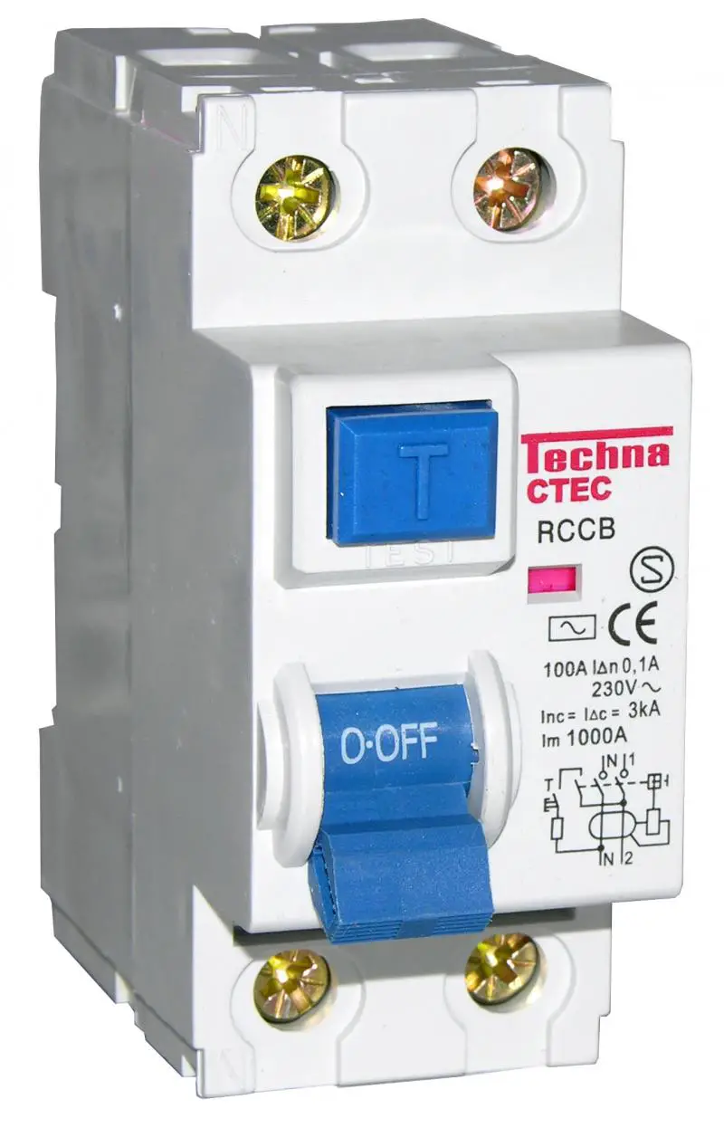
Could look similar to this
You would be looking for a test button, once pressed, you should have power loss to the protected circuits. To re-energise, the dolly switch is put back in the closed/on position.
The 17th Edition requires socket-outlets rated at up to 20 A and intended for use by ordinary persons to be provided with additional protection by means of a 30 mA RCD.
Are you also aware of the safe zoning/positioning of cables, if not take a look here
//www.diynot.com/wiki/electrics:installation_techniques:route
//www.diynot.com/wiki/electrics:installation_techniques:walls

If you are not running cables within walls, is the cable surface mounted to socket outlets then?
 
ban-all-sheds said:
Never assume.

PrenticeBoyofDerry said:
Never assume!

Fair enough, but is there actually any other explanation? If it turned out to be on a spur, what could the second cable be for?

So will your new sockets be installed in the floor, not on the walls? Or do you plan to have the cables running on the surface of the walls?

They'll be placed just above the skirting board, with the cables going out from the back of the recess directly down into the under-floor cavity.

Look to see if you have a RCD or RCBOs in your CU.

I don't think I do, but maybe I can take a picture of the CU to show you. It just has simple switches for each circuit, no test buttons or anything. It looks quite old.
 
I don't think I do, but maybe I can take a picture of the CU to show you. It just has simple switches for each circuit, no test buttons or anything. It looks quite old.
If the installation is very old, it is very likely you do not have 30mA RCD protection at the board, and may also require the earth bonding and earth conductor to be updated.

Options are remote external RCD for fuse board or circuit, Spur additional sockets with RCD fused spurs or install RCD socket outlet plates.
Or Fuse board swap
But still unsure how your cables are going to wall mounted sockets?
 
Fair enough, but is there actually any other explanation? If it turned out to be on a spur, what could the second cable be for?
Another spur?

A bridged ring?


They'll be placed just above the skirting board, with the cables going out from the back of the recess directly down into the under-floor cavity.
So they'll be concealed.


It just has simple switches for each circuit, no test buttons or anything. It looks quite old.
Then you should not be adding any new sockets.
 
I don't think I do, but maybe I can take a picture of the CU to show you. It just has simple switches for each circuit, no test buttons or anything. It looks quite old.
If the installation is very old, it is very likely you do not have 30mA RCD protection at the board, and may also require the earth bonding and earth conductor to be updated.

Options are remote external RCD for fuse board or circuit, Spur additional sockets with RCD fused spurs or install RCD socket outlet plates.
Or Fuse board swap

Ok - this is all news to me. I thought I could extend an existing installation in its current fashion and not have to bring everything up to "2013" regs as soon as I modify anything.

But still unsure how your cables are going to wall mounted sockets?

What do you want to know? I don’t know how to describe it any better, it’s just the way 99% of sockets seem to be placed. Right above the skirting board, with cable holes drilled at a slant into the wall from inside the recess, coming out at the base of the wall into the floor space, between joists etc.
 
Ok - this is all news to me. I thought I could extend an existing installation in its current fashion and not have to bring everything up to "2013" regs as soon as I modify anything.
You don't have to bring everything up to date, but any new additions should comply with the current regulations, which in this case means RCD protection for any new sockets and any new concealed cables.
 
They'll be placed just above the skirting board, with the cables going out from the back of the recess directly down into the under-floor cavity.
What do you want to know? I don’t know how to describe it any better, it’s just the way 99% of sockets seem to be placed. Right above the skirting board, with cable holes drilled at a slant into the wall from inside the recess, coming out at the base of the wall into the floor space, between joists etc.
I was not aware of this information when I posted as you didn't reply to the question, until later.
That qualify's as within wall then,(but you still need RCD for sockets regardless)
You must also give enough distance between the finished floor level and socket outlet, to prevent stress to plug and flex of appliance, so the height of the socket should be at least 150mm as a guide.
 
Ok - this is all news to me. I thought I could extend an existing installation in its current fashion and not have to bring everything up to "2013" regs as soon as I modify anything.
As BAS has already informed you.
You do not have to bring everything up to the current requirement of the wiring regulations.
But new alteration/additions that are made do. So any new cable, outlets, accessories etc. Need to be compliant.
I know this must be frustrating for you, but if you are undertaking work like this, you really need to get up to speed or employ someone who is!
 

DIYnot Local

Staff member

If you need to find a tradesperson to get your job done, please try our local search below, or if you are doing it yourself you can find suppliers local to you.

Select the supplier or trade you require, enter your location to begin your search.


Are you a trade or supplier? You can create your listing free at DIYnot Local

 
Sponsored Links
Back
Top