- Joined
- 15 Jan 2004
- Messages
- 233
- Reaction score
- 3
- Country

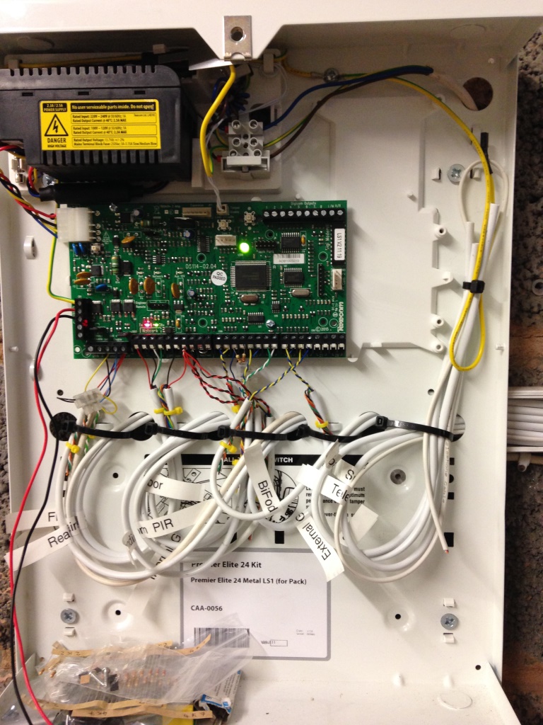
Time for another question - sorry! I've installed the panel, powered up and programmed the system through the keypad (I couldn't get the USB com to work). I did the walk tests and the bell tests and all is good. However when I put the cover back on the panel and got out of engineers mode the alarm sounded and I got a bell tamper fault displayed on the keypad.
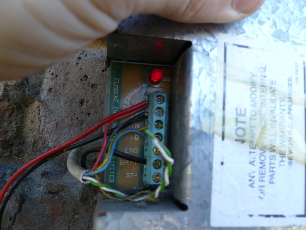
I have two bells (front and rear) and have wired them in the same way as my accord and in the sticky at the top of this section. This is what I have at the bells (ignore the extra red/black wires they are for additional comfort LEDs):
 P1070088 by Aldous Voice, on Flickr
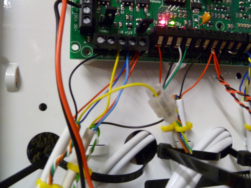
And this is what I have at the panel:
 P1070092 by Aldous Voice, on Flickr
It's hard to see but I have...
- both red wires in the +ve.
- both blue wires in the Ring
- the black wire to the rear bell is in the 0v
- the yellow wire to the front bell is in the Tamp
- the remaining black and yellow wires are connected in the chocolate block.
Can anyone see where I've gone wrong please?
I have two bells (front and rear) and have wired them in the same way as my accord and in the sticky at the top of this section. This is what I have at the bells (ignore the extra red/black wires they are for additional comfort LEDs):
 P1070088 by Aldous Voice, on Flickr
And this is what I have at the panel:
 P1070092 by Aldous Voice, on Flickr
It's hard to see but I have...
- both red wires in the +ve.
- both blue wires in the Ring
- the black wire to the rear bell is in the 0v
- the yellow wire to the front bell is in the Tamp
- the remaining black and yellow wires are connected in the chocolate block.
Can anyone see where I've gone wrong please?

 Alarm Panel