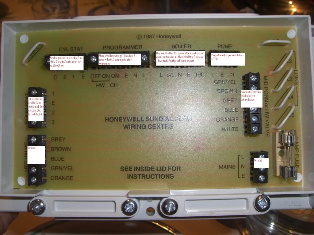
WIRING A HONEYWELL PROGRAMMER TO THE WIRING CENTRE
ST699 : Link L - 5 - 8 in Backplate. Terminal (T) 3 = CH ON. T6 = HW OFF (Y plan ONLY). T7 = HW ON
ST6400/300/200, ST712/722 : T1 = HW OFF (Y plan ONLY). T3 = HW ON. T4 = CH ON
ST1000 : Link L - 2 - 5 in Backplate. T1 = HW ON. T3 = HW OFF (Y plan ONLY). T4 = CH ON
PROBLEMS USING WIRING CENTRE
The above Wiring Centre is only suitable for (No other configuration) -
Fully Pumped systems
Y Plan (1 x V4073A Mid-Position Valve) Cut L2 & L4 (plus L3 for pump over-run boilers)
S Plan (2 x V4043H Zone Valves) Cut L4 & L5 (plus L6 for pump over-run boilers)
Gravity Hot Water, Pumped Heating system
C Plan (1 x 28mm V4043H on Hot Water side only) Cut L4 & L5 (Basic boilers only)
Wire in a Frost Thermostat exactly as stated on sticker in Wiring Centre lid.
The Boiler is continuing to run if either HTG/HW is switched off, or thermostats are turned down?
If you are using a 2 - channel programmer, ensure Link 1 is cut.
If wiring an S or C plan ensure there is no wires connected to Programmer HW OFF or CYL STAT terminal 2.
If using S plan, ensure WHITE wire is not connected in HW Valve terminal block.
Heating does not switch ON when Hot Water switched OFF?
If using Y plan ensure HW OFF and CYL STAT terminal 2 are connected. If no room thermostat is fitted, add a
link between 1 & 3 on ROOM STAT block.
Boiler does not switch off?
On BOILER terminal block, ensure L (Permanent Live) and SL (Boiler Switched Live) connections are not mixed
up.
After checking above, if still experiencing a problem remove all components and wire in one-at-a-time in the
following order- Mains, Programmer, Cylinder Thermostat, Room Thermostat, Motorised Valve(s), Boiler and then
Pump. After wiring in each component, check for correct operation and voltage using a voltmeter. This pinpoints
any faulty component very easily.


