US Green Black White cable - how to wire up in UK?

FWL_Engineer said:
If it has motors it will likely not work as the motors will be dual phase not single phase, as such the motors will need a capacitor to start them rotating. On dual or three phase this is unecessary as the phases are out of phase and automatically create the necessary stepped field.
I always thought that the split-phase system in the US resulted in the two hots being 180° apart, i.e. the voltage curves are the black and white ones, making the difference between the two the brown curve, which is exactly what the motor would see if connected between live and neutral over here....

split-phase.jpg


What have I got wrong?
 
Sponsored Links
Ban, that is exactly what I was thinking: two waveforms that are the negative of each other (i.e. antiphase). It makes sense to me!

I guess the way to wire up a device intended for this supply, but to a split-phase, would be to connect one live conductor to the neutral rail of your UK supply, and the other live conductor to the live rail of your UK supply. As Ban's graph shows, the resultant PD (the brown curve) is equivalent to the pd between a 240V live and a neutral.
 
plugwash said:
yep thats right

and green to earth ofc
Sleeved green & yellow, ofc.

In fact it might be a good idea to explicitly sleeve the other cores red&black or brown&blue, even though not required.
 
Sponsored Links
OK the pull of the matress was too great, and I was half asleep.
Here it is again, better, I hope.

Most houses in the US do indeed get either,

1) one phase and neutral. The neutral (white) is approx earth, and phase (black) flaps around to give 117VRMS (or so.)
Only seen in small flats and what we would call bedsits

2) 2 phases and earth. The 2 phases are in anti-phase, so when one goes down the other goes up. There is 110 (117 at the tranny) from each to neutral (or ground) and 220-240 between the two phases. Large loads are often connected between the two phases. Single phase loads use black white wire, regardless of which phase they use as 'hot' , but when the 2 phases come together, the 'hot' wires are usually red and black.
Such a system is seen in what we would call normal size houses.

If many parts of the states, you ask for three phase you get case 2 above (white-black-red) plus a third 'hot' blue wire, which is at ~180V to neutral or earth, whose voltage is in 90 deg phase to the direction of the other 2. This blue wire is the "wild leg".
The phase-phase voltages are still forming a triangle, but they have given you two halves of one side, and the 'height' of the triangle, rather than 3 equal radii. This is a consequence of where the transformer is earthed.
In the UK the substation transformer is a star, earthed at the centre. In the wild leg system the transformer is a delta, earthed halfway accross the base.
This additional stuff is not relevent to the questioner originally, but thrown in to explain why 3 phase in the US is much less common, and likely to raise more quesions than it answers. (and why the man on the phone gets jittery)
This is not helped that many factories and industrial estates with their own substation do choose to wire in the european way, so the phase-phase voltage is then 208, and all 3 phases are equal to ground after all.
Hope thats better.
Mike
PS see '4 wire delta' diagram here, for what I'm on about in terms of vectors.
http://www.themeterguy.com/Theory/visualization.htm
 
How do Americans get access to both phases ? All of the plugs that I have seen have been 2 flat-pins with 110V between them ? There is a 3rd round hole on the sockets, but I had assumed that was an earth connection, if required.
 
They have different plug/sockets, to stop people plugging in 110V appliances, but read the descriptions above - it's still only 2 pins, as what they are exploiting is the potential difference between the two phases, not between each phase and neutral.

My graph was not hand drawn - I knocked up a spreadsheet with the values of SIN(n), SIN(n+180), the difference between the two and had Excel draw the chart. The voltage values really are those shown - it really does work like that.

It's just like a torch with 2 cells (or more) - you only need to connect to each end of the series of cells to get the volts.
 
jtaunton said:
How do Americans get access to both phases ? All of the plugs that I have seen have been 2 flat-pins with 110V between them ? There is a 3rd round hole on the sockets, but I had assumed that was an earth connection, if required.
Using BAS's graph, normal house 110V sockets have one pin connected to the "0V" line, and the other to (say) the black trace. There may be a third one to Earth ("ground" as they call it) but a lot of houses still have 2-pin sockets, although the backbox and front plate screws will be earthed.

Sockets that supply 220V are physically different, usually bigger and with pins forming "T" shapes rather than being parallel, and have one pin connected to the Black trace in BAS's graph, the other to the White - this doesn't represent the wiring colours! :) There will (always?) be a third, Earth pin on these.

My "you learn something every day" item for today: the fact that the US Neutral comes from a centre-tap on one coil of a delta-transformer - I'd always wondered how it worked, assuming it was star-wired! :D
 
Well, haven't been brave enough to connect it up today. Maybe I should have the weekend first and die on Monday?

How on earth did the Yanks end up with such a wacky system?
 
because 120V sucks but they were too deeply into it before they realised to easilly back out. (we backed out before it was too late)
 
So we used to be on the same system? :eek: It's not like us to do something properly - I'm amazed :eek:

Will report back how it goes when we connect it up...
 
SwindonSpark said:
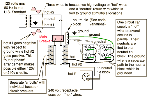
Time to reproduce my picture again eh?
Excellent, Swindon, thanks!

Now I can see why they always have twin-columns of breakers: each side is on a different phase - never realised that before! But wiring two sides to one device to get 240V, each through a seperate breaker, looks as if there's some hidden deadly danger, but I can't quite see what... something along the lines of having a fused Neutral here...

I suppose one thing could be that to isolate one socket you have to throw two breakers - and if one of them trips, a device may seem to be dead, but still has one phase connected. Hmmm...

Cheers,

Howard
 
HDRW said:
Now I can see why they always have twin-columns of breakers: each side is on a different phase - never realised that before! But wiring two sides to one device to get 240V, each through a seperate breaker, looks as if there's some hidden deadly danger, but I can't quite see what... something along the lines of having a fused Neutral here...

NO thats one of the errors in that diagram ;)

thier split boards are very much like our three phase boards in layout allowing common trip breakers to be used for cuircuits with both hot cores.
 
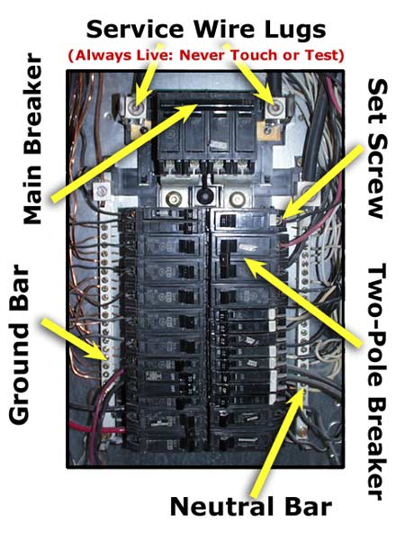
At first glance they do look as though they are physically like that, but 2-pole breakers are all on one side, not straddling two:

appliance_outlet_breakerbox.jpg


(You'll never badmouth Volex again having seen that, I'll warrant...)
 

DIYnot Local

Staff member

If you need to find a tradesperson to get your job done, please try our local search below, or if you are doing it yourself you can find suppliers local to you.

Select the supplier or trade you require, enter your location to begin your search.


Are you a trade or supplier? You can create your listing free at DIYnot Local

 
Sponsored Links
Back
Top