
You are using an out of date browser. It may not display this or other websites correctly.
You should upgrade or use an alternative browser.
You should upgrade or use an alternative browser.
Vertical header
- Thread starter Biggles..
- Start date


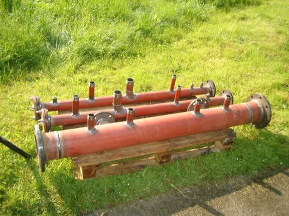
The very nice picture of the pipework is not a low loss header arrangement as used/recommended by keston boilers. Give there tech dept a call and they will fax/mail you a drawing of there idea/method for a low loss header.
The very nice picture of the pipework is not a low loss header arrangement as used/recommended by keston boilers. Give there tech dept a call and they will fax/mail you a drawing of there idea/method for a low loss header.
I'm glad you said that I thought I'd lost the plot.
Didn't look like Low Loss header to me either

Nice pipework though
B
billy bob
It is not a low loss header, it is just a flow and return header system, this is a low loss header
http://i171.photobucket.com/albums/u292/silverback_2007/DSC00884.jpg
http://i171.photobucket.com/albums/u292/silverback_2007/DSC00884.jpg
Yep that's what I call a Low Loss Header or Low Velocity Header.
Do you guys have any contacts for suppliers of manufactured LL headers?
We used to make or own a few years ago, before they became popular, but I dont have my welder contacts anymore.
Do you guys have any contacts for suppliers of manufactured LL headers?
We used to make or own a few years ago, before they became popular, but I dont have my welder contacts anymore.
Cheers, thats how we used to do them or should I say our welder did.
My then boss used to spec them up.
What did you do for design/sizes? of the vertical diameter?
Add up the cross sectional area of all F & R's and allow a bit?
or am I over simplifying it.
My then boss used to spec them up.
What did you do for design/sizes? of the vertical diameter?
Add up the cross sectional area of all F & R's and allow a bit?
or am I over simplifying it.
It is not a low loss header, it is just a flow and return header system, this is a low loss header
http://i171.photobucket.com/albums/u292/silverback_2007/DSC00884.jpg
This has about as much resemblance to a low loss header as Diyitall's first image.

Cheers, thats how we used to do them or should I say our welder did.
My then boss used to spec them up.
What did you do for design/sizes? of the vertical diameter?
Add up the cross sectional area of all F & R's and allow a bit?
or am I over simplifying it.
Its more down to flow rates, We had a chart in the office before I retired.
Lets just say too big is better than too small
B
billy bob
It is not a low loss header, it is just a flow and return header system, this is a low loss header
http://i171.photobucket.com/albums/u292/silverback_2007/DSC00884.jpg
This has about as much resemblance to a low loss header as Diyitall's first image.
You obviously do not know anything, flow and return mixing in one header equals low loss header, if you look there is a flow and return going in and a flow and return coming out, what else would you call it
B
billy bob
I was surprised they didn't stagger the the primary side billybob
I must admit so was I, but I think it is done internally, it incorparates a strainer internally to protect the two boilers that it is connected to, it is made by Spirovent.
billy bob wrote
A hydraulic decoupler.
Consisting of four connections (as your image shows) which allows the heating load to be distributed over several boilers giving higher operating efficiencies allowing some boilers to be switched off at part load operation.
Yes, as in the case of the low loss header it has negligible pressure drop over its length.
However with the low loss header or low pressure header system multiple secondary circuits can be connected directly to the header pipe with each secondary circuit requiring its own secondary circulation pump.
what else would you call it
A hydraulic decoupler.
Consisting of four connections (as your image shows) which allows the heating load to be distributed over several boilers giving higher operating efficiencies allowing some boilers to be switched off at part load operation.
Yes, as in the case of the low loss header it has negligible pressure drop over its length.
However with the low loss header or low pressure header system multiple secondary circuits can be connected directly to the header pipe with each secondary circuit requiring its own secondary circulation pump.
B
billy bob
billy bob wrote
what else would you call it
A hydraulic decoupler.
Consisting of four connections (as your image shows) which allows the heating load to be distributed over several boilers giving higher operating efficiencies allowing some boilers to be switched off at part load operation.
Yes, as in the case of the low loss header it has negligible pressure drop over its length.
However with the low loss header or low pressure header system multiple secondary circuits can be connected directly to the header pipe with each secondary circuit requiring its own secondary circulation pump.
Well I can tell you, it's a low loss header, you have been educated
You really need to look at images before you Google, there are two blanked off circuits which were for a future extension which will have its own pump or secondary circulation as you stated, I also left tappings for a third boiler to cope with the additional output
DIYnot Local
Staff member
If you need to find a tradesperson to get your job done, please try our local search below, or if you are doing it yourself you can find suppliers local to you.
Select the supplier or trade you require, enter your location to begin your search.
Please select a service and enter a location to continue...
Are you a trade or supplier? You can create your listing free at DIYnot Local
Similar threads
- Replies
- 10
- Views
- 9K
D