Wired doorbell to trigger wireless button?

obviosly theres more tech ways now :)
Like me hes from essex so i kept it simple, and the main thing it worked.
These bell posts tend to do 14 pages, with abuse and over use of the ignore button, so its early days yet.:)
 
Sponsored Links
there was me thinking everyone would know what the inside of a wireless doorbell button looks like ! :)

Like the one another member posted

soldered_push-1024x576.jpg


Endecotp, is the square thing in the middle just a push switch, would shorting across that somehow do the trick.
 
The square thing is just a switch yes.

What they're doing is not using the switch but instead applying power where the transmitter's battery is normally connected when the button is pressed. This seems to work for them, with some proviso about it taking a short time to power-up, so "jabbing" on the button doesn't work. Other transmitters might not work as well. It's not how I'd do it.

Edit: actually the power-up delay they're seeing is as likely a result of the capacitors in the voltagw regulator that they're using.
 
The square thing is just a switch yes.

What they're doing is not using the switch but instead applying power .

What i was getting at, is not what there doing, but using the ops switch with the battery in it as its supplied , removing that square switch and wiring something ?? across that to trigger it.

Intriqued now what way you have planned :)
 
Sponsored Links
If this guy's transmitter just has a switch like that, just put a transistor (C-E) across the switch and connect the B-E to the supply to the solenoid - with a suitable resistor somewhere. May need some extra bits because the supply is AC.

On the other hand, not needing a battery for the transmitter is appealing. Hmmm.
 
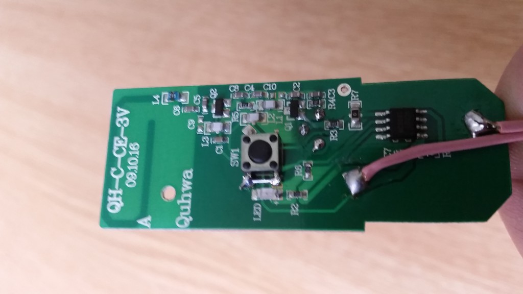
Here is the wireless button . . .
It has some fancy sensor button thing that you just touch in fact just putting your finger inside the coil without touching it sets it off but that is not a concern as there is a mounting point for a standard push button switch and shorting across (top to bottom in the pic) sets it off so this is where i would expect to connect, to make that circuit when my ringer goes off.

I tried getting a reading from the ringer box to see what sort of voltage is at the wires when pushing the door bell but i was not having much luck. the only reading i got was a lightning quick jump to around 2V but i don't know if i have the kit to be sure? Can anyone help me there also? what do i connect where with my tester below to get the information needed:

Thanks to all for the comments and suggestions, i know i am in the right place and we can get this thing working :)

Cheers for now.
 
Last edited:
I would use a baby monitor, its easier and just as portable.

DS
 
I tried getting a reading from the ringer box to see what sort of voltage is at the wires when pushing the door bell but i was not having much luck.

It's AC; was your meter set to AC volts?
 
All the components at the top right are for the touch sensor. When they detect a tpuch, current passes through U2 and Q4 to power the radio (which is most of the components in the middle). Or, when you press the not-fitted mechanical switch, current bypasses all of that to also power the radio.

So it would make sense to remove the battery and feed in 1.5V via the connection for the mechanical switch. Your challenge is to convert whatever voltage is present on your chime to the 1.5V that the radio needs. Lots of 1.5V regulators exist but most are in tiny surface-mount packages that are impossible to hand solder. More usefully there is this: http://www.digikey.co.uk/product-de.../MCP1702-1502E-TO/MCP1702-1502E-TO-ND/2179255 . Now the issue is that a 38p component has a large P&P charge; can you find a "free P&P" source for a "1.5V TO92 regulator"? You'll also need a smoothing capacitor or two and probably a rectifier diode. Alternative circuits use more, but more readily-available, components.

I'm going out now; will post more later when we know what voltage is across the chime solenoid.
 
meter on ACV 200 and measure between the red and blue single wires with the bell button held in
 
easiest home made contraption would be to use a 2 pole relay where one set of normally open contacts operates the original bell and the 2nd set of contacts operate the 2nd wireless bell contacts, the relay can be powered by the original bell transformer low voltage rectified and smoothed by a capacitor . There is no point in supplying wireless transmitter with any permanent power as their internal 12v batteries can last for well over a year, I haven't changed my wireless bell transmitter battery for nearly 5 years!

You only need to supply power to wireless receiver as that can consume 3 x AA 1.5v cells every 6 to 8 months due to continuous drain., so one could use a 5v regulator to supply it with permanent power.

The relay ensures wireless transmitter dc voltage never gets mixed with bells AC voltage. and a relay can operate with just a single diode rectifier and capacitor.

OP, if you need a schematic drawing how to do it just give us a shout.

(bear in mind wireless door bells have tendency to be unreliable as the distance becomes greater, the range suffers, so you may even have to place the transmitter mid way in your home for it to reach your outbuilding office.) 100m range is specified in clear field, usually they have problem even at 20m range indoors through walls and general building layout.)
 
Last edited:
meter on ACV 200 and measure between the red and blue single wires with the bell button held in
I am not sure which two would have been the signal wires but reading across the top two in the picture gives 14V without the button in then down to 8V when pushed. Reading from the top right to bottom left gives 14V down to 1V when pushed.

Thank you for the help in getting a reading, we are getting closer :)
 
I would use a baby monitor, its easier and just as portable.

DS
Love this idea, solves the problem but does need me to buy more kit and not use what i have, one to remember though for sure, thanks.
 
I'm going out now; will post more later when we know what voltage is across the chime solenoid.

As posted earlier i took a reading across the top two terminals and it was showing 14V without the button pushed and dropping to 8V when pushed, I'm not sure i understand why there is always voltage there but thats why i am the one asking all the questions !
 

DIYnot Local

Staff member

If you need to find a tradesperson to get your job done, please try our local search below, or if you are doing it yourself you can find suppliers local to you.

Select the supplier or trade you require, enter your location to begin your search.


Are you a trade or supplier? You can create your listing free at DIYnot Local

 
Sponsored Links
Back
Top