Wiring a light switch - old to new

Joined
27 Aug 2024
Messages
15
Reaction score
1
Country
United Kingdom
Hi Guys,

Can someone please help me:
1.Identify whether this switch will be safe to wire
2. Which wires need to go where?

These old electrical set ups really confuse me!

Thank you.

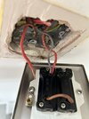
Old switch wiring (The loose red wire was in one side of the red bridge. The loose live red and brown wires came out of other side terminal):

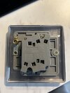
New switch back. Brass double switch.
 

Attachments

  • IMG_1961.jpg
    IMG_1961.jpg
    224 KB · Views: 78
  • IMG_1962.jpg
    IMG_1962.jpg
    210.5 KB · Views: 77
Sponsored Links
Yes ,your new switch is suitable. It must be earthed ,your old one was not .
Your new switch has the two gangs laid out in triangular fashion ,opposing each other ( one triangle points up ,the other down),
So ,com 1, L11,and L12 are one switch gang .
Com2 , L21, and L 22 are the other gang.
Your old switches gangs are laid out next to each other ,both the same way up ,so your short brown bridge wire probably won't reach between the two Com terminals.
 
Last edited:
Yes ,your new switch is suitable. It must be earthed ,your old one was not .
Your new switch has the two gangs laid out in triangular fashion ,opposing each other ( one triangle points up ,the other down),
So ,com 1, L11,and L12 are one switch gang .
Com2 , L21, and L 22 are the other gang.
Your old switches gangs are laid out next to each other ,both the same way up ,so your short brown bridge wire probably won't reach between the two Com terminals.
Hi Terry, appreciate the reply.

So in terms of earthing, will I need a professional in most likely? I'm not able to rewire myself basically, I could simply re-position what is already there.

The brown bridge wire does reach com to com on the new switch, as I did check before. So not sure if that helps at all and would allow me to proceed?

Cheers
 
The earth wires ( sleeved yellow / green) are visible in your pic and appear to be terminated in the mounting box terminal. You can either remove them from there and put them together in the switch plates earth terminal,or just add an extra length of cable from the mounting box earth terminal to the switchplates earth terminal.
 
Sponsored Links
The earth wires ( sleeved yellow / green) are visible in your pic and appear to be terminated in the mounting box terminal. You can either remove them from there and put them together in the switch plates earth terminal,or just add an extra length of cable from the mounting box earth terminal to the switchplates earth terminal.
Hi Terry, sorry me again.
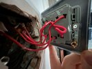
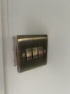
I have the same switch but 3 gang in another room which builders fit for me. I've had a look at that one and it's not earthed either. I've photo'd the configuration.
Is this essentially not safe then? I've got a few of these brass switches around they wired in and was just adding a final one. Cheers,
 

Attachments

  • image0 (5).jpeg
    image0 (5).jpeg
    274.4 KB · Views: 31
  • IMG_1963.jpg
    IMG_1963.jpg
    115 KB · Views: 35
They need to be earthed. They probably think that the screws that connect the switchplate to the metal mounting box is sufficient,it is not.
 
They need to be earthed. They probably think that the screws that connect the switchplate to the metal mounting box is sufficient,it is not.

As above. As a decorator, if I remove the faceplate screws to, for example, paper around the switch, when unscrewed from the back box and pulled forward, a live cable could pop out and hit the face plate.

I prefer electricians that earth the face plate and run an earth back to the back box. In the event that when I remove the faceplate screws, if a live pops out and hits the metal backbox, my wallpaper paste or filler is not going to become live.

It takes minutes to earth the faceplate and run a live to the metal back box. Why not do it?
 
Thanks for the help all. So turns out I have a bigger issue than I first thought as I have at least 4 brass switches that are only earthed via the backplate.

With the new one I’m fitting, I have been able to get the earth wires to the faceplate, but not sure which other wire goes where if anyone can help? I tried but failed.

To confirm, I have 2 lights plus an extractor fan I need to come on with the left switch.

Wires I have:
From the left wire: 1 red, 1 grey and 1 brown
From the right wire: 2 red wires
 
Wires I have:
From the left wire: 1 red, 1 grey and 1 brown
From the right wire: 2 red wires
Don't really understand the above ?
In your first post and pic ,there are 3 wires that are not connected,2 red,and 1 brown. Do you know exactly which switch/s terminals those 3 were originally connected to ?
And did you subsequently put any markings on all the red wires before removing the old switch so you did not get them mixed up with each other ?
No unfortunately these other wires came out when I removed the switch!

My photo isn’t great. But the grey and red connected are actually both coming from separate wires, left and right.

The other red from the right and brown from the left side went into L1.

The final red wire from the left goes into Com2.

I don’t know which wire does which sadly.
 
Pics of what you currently have connected to the new switch would be a start ,and would be better than the descriptions.
And did you subsequently put any markings on all the red wires before removing the old switch so you did not get them mixed up with each other ?
And an answer to the above would be helpful
 
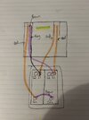
So I’ve rewired the old switch back in for now so it’s at least working. I’ve tried to draw out the current configuration as apologies I know my photos and explaining hasn’t been very clear. Currently each switch turns a different light on, but isn’t powering the extractor fan which is was before so I have changed something here. Unfortunately I didn’t get to label them as most came out straight away.
 

Attachments

  • IMG_1965.jpeg
    IMG_1965.jpeg
    212.5 KB · Views: 30
Do the two red wires on the right side of the mounting box both come from the same cable ?
On the right side of the mounting box there is a red wire ,does that come from a cable that also has a black wire coming from it that goes into a connector block with another black wire/s ?
Do you have any voltage testing instruments ?
 

DIYnot Local

Staff member

If you need to find a tradesperson to get your job done, please try our local search below, or if you are doing it yourself you can find suppliers local to you.

Select the supplier or trade you require, enter your location to begin your search.


Are you a trade or supplier? You can create your listing free at DIYnot Local

 
Sponsored Links
Back
Top