Hello all,
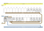
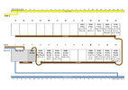
(Dual Row CU, All RCBOs, Wiring Diagram?)
We're fitting a new bathroom with electric shower etc and our existing CU is already full.
It's a 13 slot hager, 63 amp main fuse, with one RCD for socket circuits and pretty much everything
else direct on MCBs. Fairly ancient. (Based in Ireland).
Originally I talked to our electrician about installing a 2nd CU, but we've since agreed to install
a bigger unit and combine all circuits into one. It's a bit tricky and we might have to run two CUs
temporarily on split tails. The electrician will be testing all the existing circuits initially, but I suspect
we might be into some rewiring as part of the process. See at the time. He's due to start in
the next few weeks.
I said I'd get enough hardware to sort the bathroom as a starter and he advised tell the distributor what
circuits we want supported initially and they'll spec out the kit. That's done and we've received a Hager Gamma Dual Row - 26 Modules,
4 RCBOs, and 1 x 63Amp MCB (which apparently acts as the main fuse). I like the idea of RCBOs for all circuits,
and subject to the electricians thoughts I'm inclined to go that route for the rest.
My own background is in IT, comms networking, and I'm a sucker for network diagrams
so thought I'd try a layout for the CU ! They help me understand how things connect etc, and also might make
it easier to have a discussion with the electrician about module distribution when work starts.
But I'm scratching my head about a few things:
1 - The MCB that acts as the main fuse - does that sit before or after the main switch.
2 - How is the Line In to the busbar on row 1 extended to the busbar on row 2.
I've done a couple of diagrams exploring the MCB (main fuse) position, and have assumed that
connecting the busbars is just done with some appropriate flex, but on that latter point
it seems there might be different ways of doing that too. Would the flex share a connection to
the busbar with an RCBO, would it originate from the main switch, or are there some sort of
terminals that could sit on both busbars and provide a dedicated connection between them.
This part of the setup has me stumped.
I know the electrician will just come in, do what he does, and I could just wait until it's done to find out,
but my curiosity is getting the better of me! Basically where does that 63Amp MCB go, how is it connected,
and how is the 2nd busbar integrated into the system.
I'm anticipating there's probably a number of ways to skin the cat, but would love to hear if
I'm wildly off the mark or heading somewhere in the right direction.
My two (stab at it) diagrams attached! Thanks for any pointers.
Attachments
Last edited:


