12v lights

The idea of using series connections and a higher voltage is a good way to reduce current and hence cable diameter.
Agreed - certainly as an intellectual exercise. However, in the real world I think one has to try to keep one's feet on floor (and I'm very guilty of often not doing that!) and repeatedly ask oneself how much time,effort, cost and 'complexity' (and 'complexity' can result in reduced reliability) is justified as a means of avoiding buying and installing fatter cable.

Put a suitable zener diode across each lamp so that in the event of a lamp buring out the series chain to other lamps is maintained.
Maybe - but it would obvioulsy have to be a pretty fat zener, maybe with a heatsink, to cope with the sort of power dissipation we would be talking about for any significant period of time. Some provision for reverse polarity protection of the supply (which would probably involve a small voltage drop) would then ideally be desirable

Instead of using an invertor to convert 12 volts to a higher voltage use two or more 12 volt batteries in series to get the voltage. This is not going to be much more expensive as the batteries can be smaller capacity. Four batteries would give 48 volts which is regarded as ELV and therefore safe for outdoor use
Fair enough.

The The 12 volt generator is connected across one battery at a time. Charge battery A for 15 minutes, then move it to battery B and charge for 15 minutesm then C then D. Four relays and a simple timer circuit will do the connections automatically.
You could then also have a fifth battery charged for other equipment.
Fine so long as the output of the generator is 'floating' relative to the battery/light circuit - which presumably would be the case if the latter were SELV.

However, as above, whether all that would be justfied as a means of avoiding larger (not necessarily massive) cable is another matter!

Kind Regards, John.
 
Sponsored Links
I would certainly question to appropriateness of designing on the basis of 20 degrees - even in the UK, and even with no current flowing in the cable, ambient temperatures of 30 degrees or more are far from impossible. However, it would seem that, now you have put the thought into my mind, it would nearly always be reasonable to calculate on the basis of a temperature considerably less than 70 degrees. Do people actually do this, since I can't say I've ever seen it done?
I'm amazed that the 70°C values should be used for calculations related to cables running at their normal operating temperatures. A footnote to Tables 41.2 etc., which give the maximum earth fault loop impedance, says the impedance given should not be exceeded when the conductors are at their normal operating temperature.

I've never come across a cable operating at 70°C in a house or elsewhere for that matter (excl pyro). Had I come across such I'd be looking for a fault. 60°C will cause 2nd degree burns with 3 seconds exposure.

If the designers use the 70°C values, they will get the wrong answer for the maximum loop impedance. That may be fail safe but it is unquestionably unprofessional and indicative of laziness in not looking up he 20°C figure. There's a table of 20°C values in the on-site guide.
 
I'm amazed that the 70°C values should be used for calculations related to cables running at their normal operating temperatures. A footnote to Tables 41.2 etc., which give the maximum earth fault loop impedance, says the impedance given should not be exceeded when the conductors are at their normal operating temperature.
I've never come across a cable operating at 70°C in a house or elsewhere for that matter (excl pyro). Had I come across such I'd be looking for a fault. 60°C will cause 2nd degree burns with 3 seconds exposure.
If the designers use the 70°C values, they will get the wrong answer for the maximum loop impedance. That may be fail safe but it is unquestionably unprofessional and indicative of laziness in not looking up the ....
I agree with all that, and maybe I've misunderstood, but whenever I've seen electricians talking about, or calculating, voltage drops, in this and other forums/fora, they always seem to be using the (70°C) figures from Tables such as 4D2B.

....it is unquestionably unprofessional and indicative of laziness in not looking up he 20°C figure. There's a table of 20°C values in the on-site guide.
As I said, this is where we differ. I think it is at least as wrong (actually more wrong, since it's moving in the 'bad' direction), and certainly at least as unprofessional, to use a 20°C figure as it is to use the 70°C one - as I said, even with no current flowing, many cables will normally be at temperatures above 20°C (at least at certain times of year), and when current is flowing the temperature will obvioulsy rise to at least some extent.

Maybe this is the issue. Rather than due to the unprofessionalism and laziness you suggest, maybe people adopt the conservative approach of using 70°C figures because of the difficulty in estimating the 'normal operating temperature', under load. It will presumably be somewhere between 20°C and 70°C - but deciding where within that range would involve a detailed analysis of the precise installation method and calculations which I would dare to suggest may not be familiar to a lot of electricians. I must admit that I was under the impression that (perhaps for the reasons I've just stated) it had become the convention amongst electricians to use the conservative 70°C figures for VD calculations in domestic installations - but maybe I'm wrong.

Kind Regards, John
 
I'm amazed that the 70°C values should be used for calculations related to cables running at their normal operating temperatures. A footnote to Tables 41.2 etc., which give the maximum earth fault loop impedance, says the impedance given should not be exceeded when the conductors are at their normal operating temperature.

Without going into the maths it does seem from the various voltage drop tables published that the amount of cooling available to a cable has a significant affect on its resistance.

Clipped to a wall~~touching plaster board~~in insulation~~metal cable tray~~ perforated metal cable tray~~ all give different voltage drops for the same cable at the same current load.

Which suggests the temperature of the copper is high enough to require cooling during normal operation. So what is the normal temperature of the copper inside the PVC ?

So working with the worse case of 70°C may be necessary.
 
Sponsored Links
HI me again thank you all for your time, but my problem is still here. The distances for the lights are from battery to light battery to light and so on.Would it be essayer to put in a 400w inverter then voltage regulator 0.5 2 core then transformers to each 12v light
 
HI me again thank you all for your time, but my problem is still here. The distances for the lights are from battery to light battery to light and so on.Would it be essayer to put in a 400w inverter then voltage regulator 0.5 2 core then transformers to each 12v light
Not the way I would tackle it as it then involved mains type voltages and the need to protect the cables in line with mains voltage hazards. With under 50 volts the hazards are far fewer and single insulated automobile type wiring can be used.

Also with inverters at 90% efficiency you will lose as much energy in the inverter and transformers as you would with 12 volts on undersized cables
 
HI me again thank you all for your time, but my problem is still here. The distances for the lights are from battery to light battery to light and so on.Would it be essayer to put in a 400w inverter then voltage regulator 0.5 2 core then transformers to each 12v light
As Bernard has says, I wouldn't personally favour that option, for the reasons he gives.

The protracted discussions which have been going on here are all very well, but the simplest solution is very often the best one. As various people has said, the exact optimal wiring arrangement depends to some extent on the 'layout' of your lights - but, if it were me, I'd forget all the 'clever stuff' and simply use whatever cable it takes - probably one or two rings, probably of 4mm² cable. If you can give us some indication of the layout of the lights, we might be able to be more specific in our suggestions.

Kind Regards, John.
 
So what is the normal temperature of the copper inside the PVC ?
Depends on installation method and the current flowing.


So working with the worse case of 70°C may be necessary.
It is safe, but not always necessary.

A 6A lighting circuit cannot carry more than (as in Ib may not legitimately exceed) 6A.

Ignoring any ambient temperature or grouping factors, Iz for 1.5mm² will be at least 10A, and so it will never get to 70°C and so the voltage drop will never get to 29mV/A/m.

If using the VD at 70°C causes no design issues, the use it and move on, but if it does then why not take a closer look?

The problem, of course, is doing the calculations for non-adiabatic temperature rise in the cable (possibly in several sections of the cable).
 
The problem, of course, is doing the calculations for non-adiabatic temperature rise in the cable (possibly in several sections of the cable).
Exactly - and. as I wrote to Stoday, I suspect this is the reason why many/most people probably take the conservative and easy route of working with 70°C figures for domestic installations. Although the difference is 'significant', it's far from enormous. Perhaps most important of all, this approach is, I would think, very unlikely to make any difference in relation to an LV lighting circuit in a 'normal house' - i.e. it is unlikely to indicate that the VD with 1mm² cable, let alone 1.5mm², is unacceptable, and using a cable <1mm² is not an option. So, except for the engineering purist, what is the point in engaging in time-consuming estimation of cable operating temperature, hence more precise estimation of VD, if it is not going to make any difference, anyway?

Kind Regards, John.
 
I had a quick google for a cable temperature rise calculator.

Didn't spend much time on it, and didn't find one, but I did find this:

http://www.electriciansblog.co.uk/2009/12/voltage-drop-calculation/

"The resulting volt drop must then be multiplied by a factor of 1.20. This is the factor from table 9C in the on site guide to correct for the rise in temperature when the circuit is under load."

So this guy proposes to use a mV/A/m value from Appendix 4 of the regs or Appendix 6 of the OSG, which already assume a conductor temperature of 70°C, and then multiply the result by 1.2 to allow for a temperature rise from 20°C to 70°C.

I despair, I really do.

And people wonder why when we get trainee electricians here who are clearly struggling with basic maths I advise them to choose another career...
 
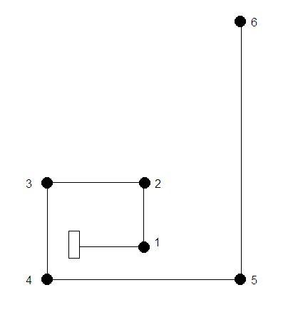
The layout of the lights are, battery bank then through wall 2m right no1 light from battery 2m left no2 light from battery 3m left another room no3 light from battery 3m left no4 light from battery 6m left no5 from battery 8m left no6 and last light, All light have own on/off switches. 12v 20w
 
The layout of the lights are, battery bank then through wall 2m right no1 light from battery 2m left no2 light from battery 3m left another room no3 light from battery 3m left no4 light from battery 6m left no5 from battery 8m left no6 and last light, All light have own on/off switches. 12v 20w
Do you mean roughly like this:
If so,I reckon there are probably some pretty efficient wiring layouts which could be contemplated.

Kind Regards, John
 
The consideration as always is cost. To use inverters is expensive and if you have ample power then there are cheaper methods.

It does not matter is fixed resistor or a semi conductor device unless using switch mode you are generating heat.

The first simple method will not work as individually switched so either some type of semi conductor or individual cables to each lamp.

There are many ways to boost voltage from replacing full wave rectifiers with half wave and charging one battery from pos half and other on neg half to just varying the regulation.

I saw with Cat the idea of using 8 volt instead of 6 volt batteries and this could be used to combat volt drop.

But if you consider the cost then a separate cable to each lamp is likely most cost effective method.

Although you have said 12v 20W what type of lamp are you using? I would hope either LED or discharge with an inverter either way there will be a latitude in voltage required.

It would seem daft to use tungsten lamps and inverters as the LED or discharge lamp have a greater latitude in first place. Even with tungsten lamps what type. I would hope automotive types.

Until you say exactly what you have we are waiting time.
 
From battery through wall 2m right no2 no3 is right no4 sits at 2oclock off no2 no5 sits 10oclock off no4 and no6 sits 12oclock off no5
 

DIYnot Local

Staff member

If you need to find a tradesperson to get your job done, please try our local search below, or if you are doing it yourself you can find suppliers local to you.

Select the supplier or trade you require, enter your location to begin your search.


Are you a trade or supplier? You can create your listing free at DIYnot Local

 
Sponsored Links
Back
Top