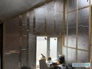
Hello,
I'm adding a non load bearing stud wall to the perimeter of my kitchen in effort to internally insulate my granite home. The stud wall will allow a 50mm or so cavity between stud and granite and will be built of 4"/2" stud with 50mm celotex between studs, and 25mm sheets over top of that to avoid thermal bridging and condensation through the studs. Then there'll be a damp proof sheet over that before finishing in plasterboard.
I've attached a stock photo of what my wall might look like before covering in the final sheet of celotex and plasterboard - my question is how to run cable and how to fit sockets? If, like in the photo, PIR sits flush with the inside of the stud wall, how do I avoid air gaps and thermal bridges when cutting big rectangular holes in the PIR for sockets? If the PIR should instead be pushed to the back, why do all internet images appear like the one attached with flush fit and silvertape over studs? Should cable be run behind the PIR in the cavity?


