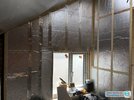
Adding Cables and Sockets in Kitchen Stud Wall Insulated with PIR

Joined
2 Jul 2009
Messages
17
Reaction score
1
Location
Aberdeen
Country
United Kingdom
Hello,

I'm adding a non load bearing stud wall to the perimeter of my kitchen in effort to internally insulate my granite home. The stud wall will allow a 50mm or so cavity between stud and granite and will be built of 4"/2" stud with 50mm celotex between studs, and 25mm sheets over top of that to avoid thermal bridging and condensation through the studs. Then there'll be a damp proof sheet over that before finishing in plasterboard.

I've attached a stock photo of what my wall might look like before covering in the final sheet of celotex and plasterboard - my question is how to run cable and how to fit sockets? If, like in the photo, PIR sits flush with the inside of the stud wall, how do I avoid air gaps and thermal bridges when cutting big rectangular holes in the PIR for sockets? If the PIR should instead be pushed to the back, why do all internet images appear like the one attached with flush fit and silvertape over studs? Should cable be run behind the PIR in the cavity?
 

Attachments

  • PIR wall.jpg
    PIR wall.jpg
    84.3 KB · Views: 263
Sponsored Links
Are the walls uneven? If not I think I'd be trapping the celotex against the wall with battens, taping the joints and then the battens form a service void that the wires run in.

Leave a gap between (or cut a notch in) the vertical battens at 500mm off the floor, then that's the route the wire takes horizontally. Vertically it can go anywhere between a batten. Back boxes for plasterboard exist, they have ears that grip the edges of the hole in the plasterboard that you cut to fit the back box. A service void of 25mm plus PB of 12 mm means you can fit a 37mm back box without having to hollow out the PIR any, and it's deep enough to cope with plumbing too

The service void allows the silver surface of the PIR to work as intended; it can't reflect radiant heat if it's in conductive contact with something. The effect isn't massive, maybe improving U by 0.01, but it's there


If the walls are uneven and you're building a stud wall to even them up you could channel the 25mm PIR out. Bear in mind what installation method this results in your wiring adopting and rate the cables accordingly
 
I've given a good* approach above. Here is a recap, inside to outside:

Plasterboard
Battens to form service void and clamp below following layers to studs
Vapour Control layer
Insulation
Studs with insulation between
OSB sheathing (if there are particular structural concerns for this wall)
Breather membrane
Cavity
Existing wall


Sockets etc mount to the plasterboard


If you're looking to insulate an existing wall in good dry condition you can skip the cavity and studs and just use battens to clamp the VCL and insulation to the wall. Life might get easier if you bond the insulation to the wall first with expanding foam

*"best" is subjective
 
Last edited:
Sponsored Links
I've given a good* approach above. Here is a recap, inside to outside:

Plasterboard
Battens to form service void and clamp below following layers to studs
Vapour Control layer
Insulation
Studs with insulation between
OSB sheathing (if there are particular structural concerns for this wall)
Breather membrane
Cavity
Existing wall


Sockets etc mount to the plasterboard


If you're looking to insulate an existing wall in good dry condition you can skip the cavity and studs and just use battens to clamp the VCL and insulation to the wall. Life might get easier if you bond the insulation to the wall first with expanding foam

*"best" is subjective
Unfortunately the face of our studs are positioned so that the PB sheet meets flush with decorative stone & brick window reveals. Adding a batten layer would bring us out too far. I did post our scenario but no responses yet
 
Hi @JKBDIY . What did you do in the end? I’m about to do similar and scouring the forums for best approach. TY
Hi Will, I ended up building studwall as I described above. All cables were in the cavity, then poked through small holes in the 50mm PIR. Dryline 35mm backboxes could then be used (using cutout into the 25mm PIR, the rest of the depth taken up by plasterboard and skimcoat).
 
Hi Will, I ended up building studwall as I described above. All cables were in the cavity, then poked through small holes in the 50mm PIR. Dryline 35mm backboxes could then be used (using cutout into the 25mm PIR, the rest of the depth taken up by plasterboard and skimcoat).
Thanks. In regard to cable rating, what reference method / installation method did you design to? Within insulated wall or free air?
 

DIYnot Local

Staff member

If you need to find a tradesperson to get your job done, please try our local search below, or if you are doing it yourself you can find suppliers local to you.

Select the supplier or trade you require, enter your location to begin your search.


Are you a trade or supplier? You can create your listing free at DIYnot Local

 
Back
Top